Interior Trim

Our trim is made from locally-harvested maple in a #1 common grade, which is relatively free of knots but has quite a bit of character. Rather than using a typical molded profile for the baseboards and casings, we decided to use a simple rectangular profile to highlight the beauty of the wood. Our cabinetmaker Jack milled most of the trim 3/4″ thick and 3″ wide for the baseboards and casings for the doors and windows.

January 26, 2010
The painters sprayed two coats of Sher-Wood Kem Aqua water-base lacquer onto the first batch of interior trim boards, along with the cabinets for the cottage kitchen and bath. The first photo below shows Scott applying the lacquer, and the second photo shows the trim boards drying. After these two coats are dry, they’ll sand them and spray on two more coats.

February 5, 2010
With the interior floors done, Dan and Bruce started installing the interior doors and the maple trim around them. The first photo below shows one of the bedroom doors in the cottage, and the second shows the door into the pantry of the main house. This lets a lot of light in from the exterior pantry door, so that the hallway area has plenty of natural light.

February 13, 2010
Liz cleaned and painted the antique leaded glass window that will go over the sink in the main kitchen. Dan built a frame for it out of maple trim.

February 18, 2010
Dan mounted and framed the window in the opening over the sink. The trim on the inside will be added after the cabinets are installed.

Bruce applied spray foam insulation to the open tops of the window seats, to seal in the cellulose insulation below. After it was trimmed with a hand saw it left a flat surface for mounting the window seats.

February 19, 2010
Dan trimmed and mounted the maple window seats underneath the large south windows in the main house and under the south window of the cottage. These are glued-up maple boards 3/4″ thick and about 14″ wide.

Each window seat is long enough to seat 6 or 7 people, or about 20 cats!

Solar Heat Plumbing

Includes affiliate links that help offset our expenses at no cost to you. Affiliate programs and affiliations include Amazon Associates and the eBay Partner Network.

This page shows photos of the plumbing system that transfers heat from the solar heat collectors to the heat storage tank. For a discussion of the technical design behind this system, click here.

December 21, 2009
Our plumber finished installing the plumbing for this system today.The first photo below shows the completed solar heat plumbing system, and the second photo is a side view showing the connections into the heat exchangers in the heat storage tank.

The fluid will flow clockwise in this photo, with the hot fluid from the top of the heat collectors coming down on the upper right. The flow splits in two and enters the tops of two of the heat exchanger coils. Each coil is a 100 foot length of 3/4″ diameter copper tubing, and the heated fluid spirals downward through the coils, then the cooled fluid comes up and out the two pipes on the bottom of the photo. Here the two parallel flows recombine and enter the pump, which circulates the fluid back up to the bottom of the heat collectors to be heated again by the sun.

December 23, 2009
After pressure testing the system it was time to clean it and prime it. The photo below shows the Wayne 1/2 HP Transfer Pump that we used to prime the system. The pump draws the fluid from the 30-gallon tub on the floor and pumps it into the solar loop. Once the loop is full the fluid starts running back out the outlet hose and back into the tub. The fluid looks really dark in this picture but it’s actually light pink.

Here’s a photo of the connections for priming. The outlet of the transfer pump goes to the connection on the left hand side, and the return from the solar loop exits out the hose on the right hand side and returns to the tub. The valves next to the pump let us close it off, so we’re pushing the fluid through the system without using the circulation pump.

First we pumped in a solution of TSP-PF Cleaner, to clean out any solder flux or other residue from inside the pipes and solar collectors. Then we flushed the system with plain water, to rinse out all the TSP. Finally, we filled the system with a mixture of non-toxic propylene glycol antifreeze and water, running the pump’s outlet into a pail until it turned from clear (water) to pink (glycol). Then we put the outlet back into the fill tub and circulated the solution until it seemed that all the air was out.

Based on the manufacturer’s recommendation we chose a mixture of 60% glycol to 40% water, in order to give burst protection down to -40 degrees F. The fluid may freeze solid or slushy before it gets that cold, but it won’t expand and burst the pipes until it reaches -40. It’s never gotten that cold here but it has dipped down around -20 on occasion, so a 50% glycol solution would just barely offer enough protection. And the glycol’s freeze protection degrades over time, especially after it’s been hot, so we want an extra safety margin here. The down sides of using more glycol than necessary are somewhat higher cost and lower heat transfer efficiency, but these are not significant compared to the cost of bursting pipes inside the collectors.

The antifreeze contains additives designed to inhibit corrosion and to reduce scaling in the pipes, but it’s inadvisable to use very hard water. Our well water is pretty good but it does contain a fairly high level of calcium, so it’s not the best choice for this system because it would eventually cause some calcium deposits in the pipes. Instead we used bottled “purified drinking water” from the dollar store, which is purified by reverse osmosis and only cost $1 per gallon. We tested the hardness of it and it’s much softer than our well water so it should work better.

December 24, 2009
Today Jay wired up the Heliodyne Delta-T Pro controller that controls the pump. It uses temperature sensors to measure the fluid temperature at various points in the system. The first photo below shows one of the sensors, and the second photo shows one mounted on the outlet of the solar heat collectors. After mounting the sensor, the pipe was wrapped with thick foam insulation to reduce heat loss.

The controller also has heat sensors inside the heat storage tank, and these are simply slid down inside the red PEX tubes that were installed as the tank was built. The photo on the left shows the end of the upper heat sensor tube, and the one on the right shows the end of the lower heat sensor tube. These let the controller measure the temperatures at the top and bottom of the tank, so it can activate the pump when the collectors are warm enough to heat the water in the tank.

The controller has an Ethernet interface, through which it provides a simple browser-based interface to monitor and configure it. The display below was taken late in the day after the sun had gone down, so the collectors are a chilly 37.7 degrees. The bottom of the storage tank is at 47.1, and the top of the tank (T3) is at 53.1 degrees. This is, on average, the same temperature as our well water and the tank is essentially at the same temperature as when we filled it since we haven’t collected any solar heat yet. The other temperatures are measured at the heat exchanger inlet and outlet, and they will let the collector compute how much heat energy is actually being collected once we get some sun. This page will also display the actual flow rate through the system when the pump is running.

December 29, 2009
After a couple of days of weak or no sunshine, we finally got a sunny day! The first display below shows the system running, with a collector output of 76 degrees. The bottom of the storage tank is at 53 degrees and the top is about 63 degrees. The second display shows the energy graph for today, with a peak output of 30,000 BTU/hr around noon. That’s equivalent to about 10,000 watts! Our total harvest today was about 120,000 BTU according to the controller. The average tank temperature increased by about 8 degrees today, indicating a gain of about 134,000 BTU since it contains roughly 17,000 pounds of water at the moment. It’s not surprising that these BTU values are a little different, since the accuracy of the temperature sensors is only about +/- 1 degree, and the fact that they’re pretty close substantiates that we collected somewhere around 125,000 BTU of solar energy today. That sounds fantastic but it’s only enough to heat the house for 12 hours presently. We expect to cut the heat loss quite a bit more once the windows and doors are fully caulked and weatherstripped and the HRV is in operation.

Paint

Upon the recommendation of our painter we chose Sherwin-Williams ProGreen 200 paint for the interior walls and ceilings. It’s a low-VOC paint, not quite zero-VOC but low enough to improve our indoor air quality. It had almost no noticeable odor when it was being applied, and what little odor there was dissipated quite quickly. The ceilings have two coats of the ProGreen primer, which has a flat finish, and the walls have one coat of primer plus two coats of eggshell paint.

December 19, 2009
The painters began by spraying primer on all the interior walls and ceilings. The first photo below shows the weaving studio looking east with the kitchen on the left. The second photo shows the main dining room.

The first photo below shows the main living room, with the nook on the left and the tray ceiling over the theater wall. The second photo shows the peaked window at the south end of the cottage great room.

December 22, 2009
The painters started painting in the cottage, here applying a pale yellow to the peaked soffit over the south window. The second photo shows the kitchen area on the left and the dining area on the right.

The cottage porch is a nice spring-like green. This photo doesn’t capture the color well, as in reality it looks less like pea soup and more like pale green leaves.

December 29, 2009
Painting in the cottage is nearly complete. We changed the pale yellow over the peaked soffit to a brighter sunny yellow (more about that below). The second photo below shows the middle bedroom, with pale aqua walls.

Originally we had planned to paint the nook in the main living room dark green inside and a lighter green outside, so we had the painters apply some sample greens to see how they looked. In the first photo below there’s only one coat on the inside so it looks quite uneven. We decided that it would be too much green to do the outside in green too, so we opted to make the outside an off-white like the rest of the living room and to keep the nice dark green inside with a pale blue ceiling.

January 7, 2010
The bright yellow color (Sherwin Williams’ Fun Yellow) on the soffit in the cottage great room was just a bit too much, rather like a big banana. So we cut it with one part Fun Yellow and three parts white, resulting in the soft yellow shown below. It’s still brighter and more ‘fun’ than the original pale yellow, but considerably tamer now. The second photo below shows the opposite (north) end of the great room, which will be the kitchen area, and the dining area is to the right. The big openings in the north kitchen wall are for appliance garages, which will provide storage for countertop appliances.

Here are the two cottage bedrooms. The south bedroom, on the left, will have a closet along the right-hand side of the window so the sitting area by the window ends up the same size in each bedroom. The pink foam insulation and exposed framing will be covered by a built-in bookcase and trim.

The first photo below is the west bedroom in the main house, which will be Jay’s office. The second photo is the main bedroom with a sitting alcove by the window.

Here’s the living room of the main house. The theater wall is to the right in the first photo, and you can just see the chimney for the wood stove poking down out of the ceiling. The second photo shows the main dining room, with the kitchen on the right.

The sun porch, which sits over the cistern, has cream-colored walls and a very pale blue ceiling. The second photo shows the east wall of the workshop.

Solar Electric System

December 14, 2009
We purchased S-5! clamps from Affordable Solar in order to mount the solar panels onto the standing-seam metal roof. These clamps are designed to grip the roof seam using set screws and they work with a wide variety of roofing profiles. Unfortunately the clamps weren’t compatible with the rib profile on our roofing so we had to modify them. After a few experiments we determined that a 20-degree bevel on the right-hand side would grip under the fold of the roof seam, and that we needed to enlarge the left-hand side slightly in order for the clamps to seat properly. Dan modified the aluminum clamps by bolting each one to a piece of wood and then running it over his table saw in 3 passes. The second photo below shows the profile of the clamp before and after modification.

December 15, 2009
Dan and Bruce began attaching the clamps to the metal roof. Here are two photos showing how the clamp seats around and crimps into the standing seam as the set screws are tightened. Typically these clamps will hold several hundred pounds each, and our panels only apply about 20 pounds to each clamp so they’re plenty strong.

Here’s Dan up on the ladder attaching the clamps to the roof. We used a torque wrench to calibrate the cordless drill to tighten the set screws with sufficient torque, and used a U-joint made for sockets so that the drill could tighten the set screws from a slight angle. The clamps are applied every other rib, for a 24-inch spacing as required in the mounting instructions provided by Evergreen Solar.

December 17, 2009
At last Dan and Bruce raised the first panel and clamped it in place. Each panel will get either two or three pairs of clamps depending on how it happens to fall on the 24-inch clamp spacing.

Here’s a photo of them raising the second panel into place. You can see the wire pigtails hanging out from lower left of the panel that’s already mounted. These just snap together in order to connect the panels in series.

After the first two panels were up, Jay decided that the spacing didn’t look quite right. So Dan and Bruce mounted the top-center panel next, in order to space the other panels right and left of it with the same 1-inch spacing that the clamps will impose between subsequent rows. This will space them a little closer together than before and the two panels on the right in the second photo below will have to shift a few inches leftward, framing the whole array with a narrow border of roof visible on the right and left ends. It’s not just about the energy – it has to look pretty too!

After the first row of 5 panels was done, they lowered the ladders and started on the next row down. The technique was to use a spacing board to first set the clamps at the proper distance below the row above, so that they could set the panel onto the lower clamps to support it. Then they had to reach up and tighten the clamps above between the two rows of panels, where each clamp grips both the panel above it and the one below it.

The electrical code requires that all the panels are grounded together, with a continuous ground wire that permits any one panel to be removed without breaking the ground connection to the others. This is accomplished with a special grounding clamp designed for this purpose. You can’t see it in this photo, but the bottom of the clamp is open to allow the wire to be inserted or removed. This is a continuous wire that runs to every panel in each half of the array and back to the grounding point at the inverters on the rear of the house. The wire must be no smaller than the current-carrying conductors, 10-AWG in this case.

December 18, 2009
They continued mounting panels today, and this photo shows one-half of the array completed. These 15 panels form one string, which is wired to one of the two inverters. The other 15 panels will form a completely separate string wired to the second inverter.

December 19, 2009
We had a light snow overnight, and in the morning we could see how the steep 60-degree slope helps the panels shed snow. The first photo below was taken at about 11:30 in the morning, and the second photo shows that even with only weak sunshine the panels were nearly clear by 3:30.

December 21, 2009
As it happened, the last panel was mounted in place on the winter solstice. The second photo below was taken the following day around noon, when we had some weak sunshine. Too bad the pink foam insulation spoils the color scheme, but we think it looks pretty good nonetheless.

February 3, 2010
The siding is finished on the south side, and the panels continue to shed snow quite well. This photo was taken in the morning after a light snow, and the panels were clear of snow by mid-morning.

March 5, 2010
We have waited a month and a half for the power company to go ahead with the grid connection for the solar electric system. The photos below show the dual meter socket and breaker box that connects to the inverters. The meter on the right is our regular electric meter, and the one on the left will measure the solar energy delivered to the grid. Although it was approved quite a while ago, it took about a month for them to get those big yellow stickers and they wouldn’t proceed without them.

The photo below shows the two Xantrex GT-3.3N inverters that convert the direct current coming from the solar panels into alternating current that is fed into the power grid. Our array of 30 panels is wired as two independent strings of 15 panels, with each string connected to one inverter. The system is fully functional but it remains switched off while we await final approval from the power company. However we did perform a brief test of the system as required by the power company, and it delivered just over 5000 watts AC on a mostly sunny day with a bit of haze. The panels are rated at 6150 watts DC under ideal test conditions and at best the inverters are only about 95% efficient, so we’re quite happy to get over 80% of rated power on a day that wasn’t even full sun.

Hydronic Heat

This page shows photos of the plumbing system that supplies heat to the house. Click here for a discussion of the technical design behind it.

December 7, 2009
The plumbers installed the plumbing for the hydronic heating system. They had to assemble the components with soldered copper fittings, and to fit them into a relatively confined space. They did a professional job and the second photo below shows how it looked when they were finished. The paragraphs below describe the individual parts.

In the photo below, at the very top right are the pipes that feed water through one of the heat exchanger coils in the heat storage tank, the top of which is visible as the big light-blue thing in the back. The two blue-handled valves shown in this photo enable us to channel the water through this heat exchanger, or to bypass it entirely. The bypass mode is used when the tank is cold, as it is now, so that we can use the electric water heater to heat the house without having to also heat the storage tank. The big tank is still very cold because the solar heat collectors are not connected yet. Once the tank is warmed by the sun, we’ll start channeling the water through it in order to heat the house with stored solar energy. The brass device near the center of the photo is an air eliminator, which removes bubbles and dissolved air from the water. Below it is an expansion tank that keeps the pressure relatively constant as the water expands when it is heated.

This photo shows, to the right of the gray expansion tank, the green relay box that enables each thermostat to control a pump. Below that is the EcoSmart hot water heater, which provides backup electric heat to the system when we don’t have enough heat from the solar collectors. At the moment it is set to deliver water at 100 degrees F, which gets mixed with a little of the colder water by the mixing valve to the left, and goes into the pumps at 90 degrees. We have it set this high because we’re trying to warm the house up quickly, and normally the heater will be set for about 80 degrees. As long as the solar-heated water coming out of the heat storage tank is warmer than that, the heater doesn’t switch on and we use free heat from the sun. But not today, alas, and the house isn’t up to temperature yet so we’re consuming over 6000 watts of electricity to warm up the house. That’s a lot but we need it in order to dry out the drywall compound on the walls.

The photo below shows the two pumps that circulate water through the system. The pump on the left circulates water through the radiant floor piping in the cottage, and the one on the right supplies the main house. Each one is controlled by an independent thermostat. The gauges on the left show the temperature of the warm water going to the pumps and the cooler water returning from the floors. In this photo, taken right after start-up with the floors still quite cold, the water is entering the floors at 90 degrees F and coming back at 60 degrees. That’s a huge temperature drop and not typical of what we expect once the floors are up to temperature.

The manifolds at the bottom distribute the water from each pump out to the individual loops of tubing in the floors. The clear devices on the top are flow rate meters that show the water flow rate through each loop, and when turned they operate a valve for each loop so that the flow rates can be balanced.

Drywall

November 23, 2009
The drywall was delivered and stacked into the rooms where it will be needed. Most of it was four feet wide by up to 16 feet long.

We specified low-V.O.C. adhesive to reduce emissions within the house, and moisture-resistant board for all of the bathrooms.

November 24, 2009
The crew arrived and started screwing the drywall to the ceilings. The flash on the camera accentuates the dust in the air. They started in the entryway and then moved on to the cottage.

After the cottage was done they moved on to the garage ceiling. It went a lot faster, with few cuts to make.

Here’s a photo of the cottage great room with all the drywall hung. It’s amazing how completely this changes the look and feel of the place.

November 27, 2009
The first photo below shows the drywall going up in the sunroom ceiling, and the second is in the workshop. The crew made it look easy.

As they got to the top of the workshop ceiling they had to use a scaffolding in order to reach high enough. The second photo below shows the shop with the ceiling and west wall done.

November 28, 2009
The floor is a mess (good thing we put down protective rosin paper), but the ceilings and walls are looking nice. The first photo below is taken from the southeast end of the living room looking toward the kitchen. The kitchen walls aren’t quite done yet, so you can see the yellow moisture-resistant board that covers the inside of the bathrooms. The second photo is looking from the kitchen toward the theater wall. We specified a single piece of 54″ high drywall on the top part of this wall, in order to minimize any ripples when it’s used as a projection screen, and they ran out of 54″ wide board so this wall still shows the black mesh holding back the cellulose wall insulation. What looks like a recessed lighting fixture in the foreground is actually an air intake that will pull stale air from the kitchen. We carefully sealed all of the ventilation ducts as soon as they were installed, to prevent construction dust from entering the ductwork.

November 30, 2009
The black mesh that was used to contain the insulation in the double walls also prevents the drywallers from gluing the drywall to the studs, which is normally done to make it more stable. Often the mesh itself is glued to the studs, so that drywall can be glued solidly onto the mesh, but with the mesh just stapled on this wasn’t possible. In order to make a flatter and more stable surface for the theater wall, we cut through the mesh and exposed the bare studs for gluing on the upper portion of the wall.

The first photo below shows the single 54″ high panel being applied to the wall, after running a bead of adhesive down each stud. The image from the projector will be exactly this high and 96″ wide. To finish up the living room, they hung drywall around the circular arch over the nook.

December 1, 2009
They continued to tape seams and cover screw holes throughout the house and shop. Fortunately the insulation is nearly done so we’re able to hold some heat in the house, but we still have to rely on propane burners at this point because there are still large uninsulated areas and we’re still missing most of the big south-facing windows so the largest window openings are only covered with thin plastic.

December 4, 2009
Here are a couple of photos showing the drywall after taping. The first photo is of the south window in the cottage great room, and the second photo shows the dining room in the main house.


December 9, 2009
Today they started applying the texture to the ceilings. All of the ceilings except the raised tray over the living room will have a “knock-down crow’s foot” texture. It looks like an expensive detail but it’s actually less expensive than a smooth ceiling because it takes less time. The first photo below shows them applying it to the garage ceiling. While one person sprays the “mud”, the other stamps it with a pair of brushes as shown in the second photo.

After the texture is sprayed and stamped with the brush, it leaves a stippled surface with lots of little points hanging down. They knock this down with a large flexible scraper, and the finished result looks like this.

Cottage Kitchen Cabinets

November 20, 2009
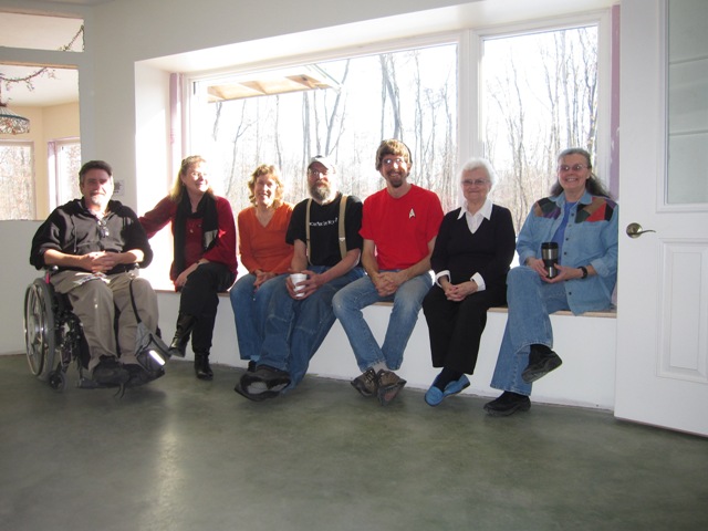
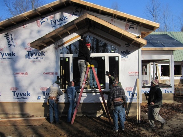
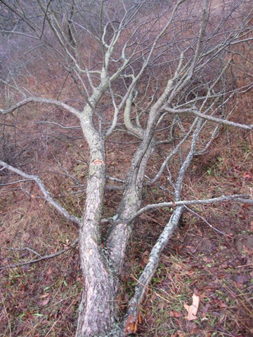
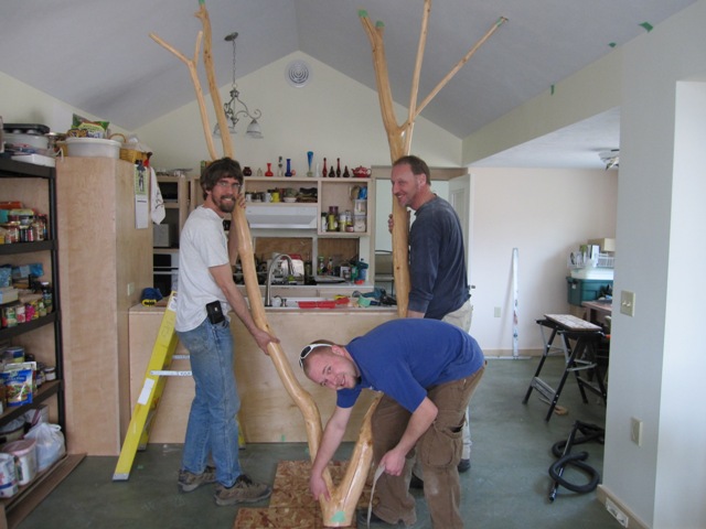
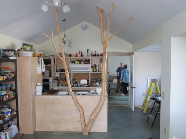
In order to support the free-standing upper cabinets of the cottage kitchen, between the kitchen and the great room, we decided to use part of a cherry tree that had to be cut as the site was graded. The second photo below – “Iwo Treema” – shows Liz, Di and Bruce testing the fit of the tree before the drywall was in. Once we got it up through the trusses, we marked the ends and cut them at ceiling level, leaving them a bit long so we can trim them to fit later.

January 26, 2010
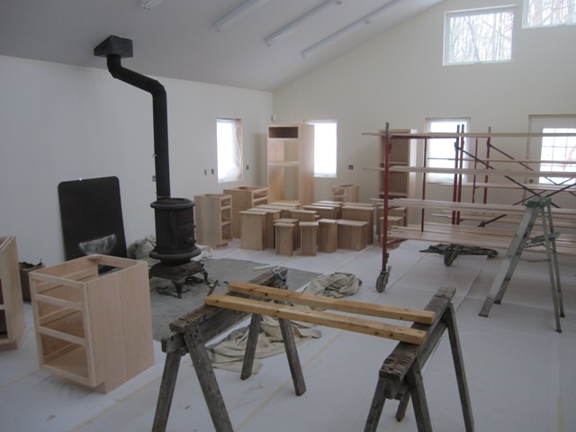
The painters sprayed two coats of Sher-Wood Kem Aqua water-base lacquer onto the cabinets for the cottage kitchen and bath, along with the first batch of interior trim. The first photo below shows the workshop full of cabinets and trim, and the second photo shows all the cabinet drawers for the cottage kitchen and bath. We chose a very simple design for the drawer fronts, with just a radius around the edges.

February 1, 2010
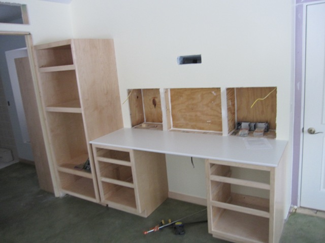
Dan started installing the cabinets in the cottage kitchen and bath.

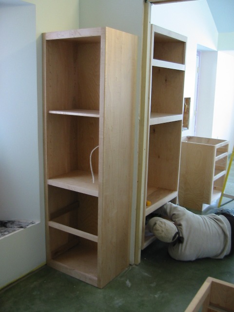
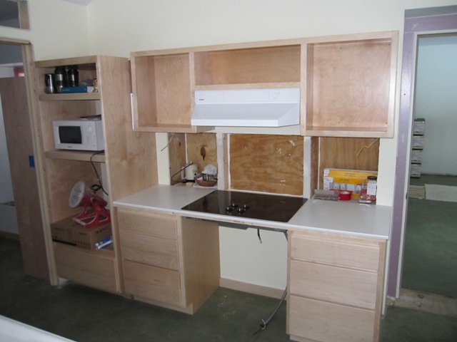
The first photo below shows the cabinets on the north wall of the cottage kitchen where the cook top will go, and the second photo shows the cabinets in the bath where the sink will go. The “countertops” are just cheap white melamine shelving, which will serve until we can get our concrete countertops made.

February 3, 2010
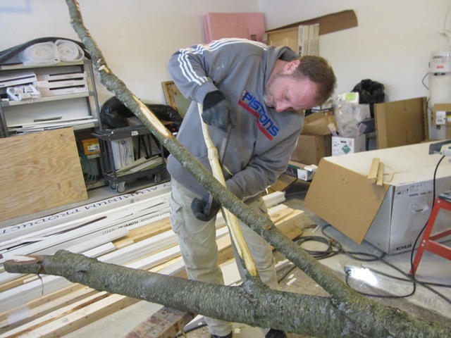
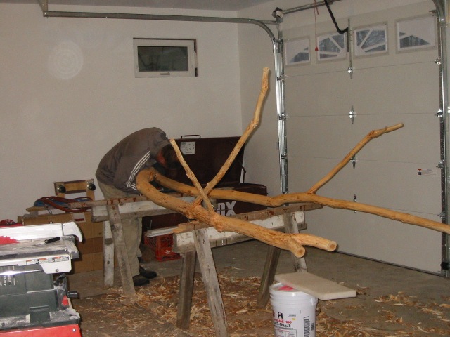
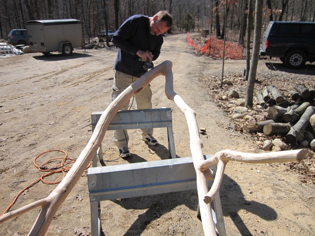
Now that we’re almost ready to mount the tree that will hold up the free-standing kitchen cabinets, Bruce started peeling it using a drawknife. The tree is still relatively “green” (wet), and we expect it to dry out and crack a bit after it’s been inside for a while. Therefore we won’t seal the surface right away, in order to let the moisture level stabilize first.

February 6, 2010
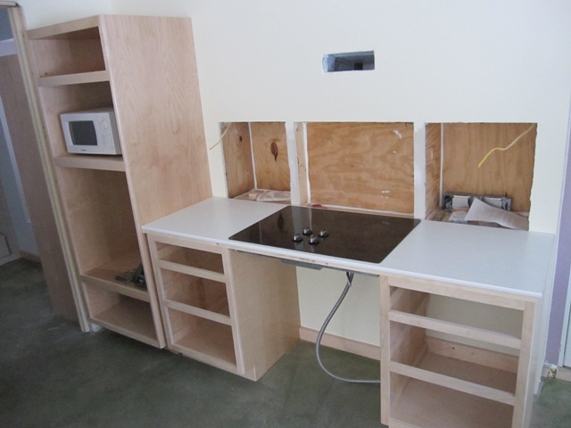
Dan cut the openings for the cottage kitchen sink and cooktop.

The sink and cooktop are mounted in the countertops but not hooked up yet.

February 10, 2010
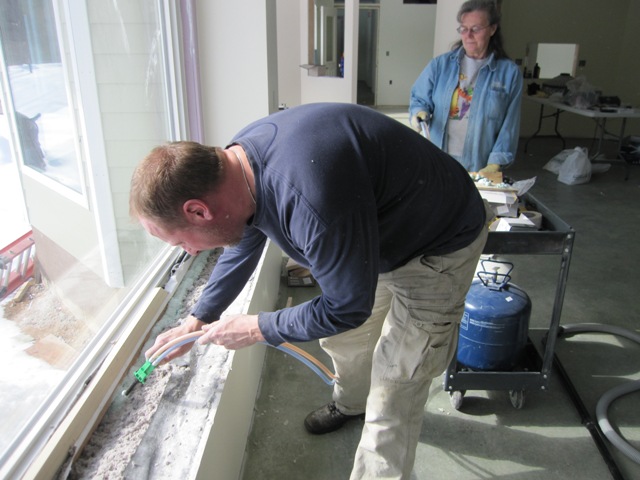
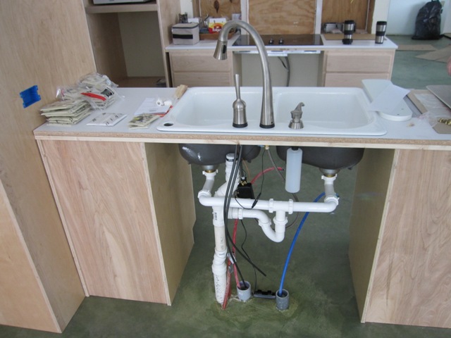
The plumbers connected the drains and faucet on the kitchen sink. The plumbing will be completely enclosed, but with knee space below the sink.

February 12, 2010
Dan mounted the upper cabinets above the cooktop and then installed the exhaust hood.

February 19, 2010
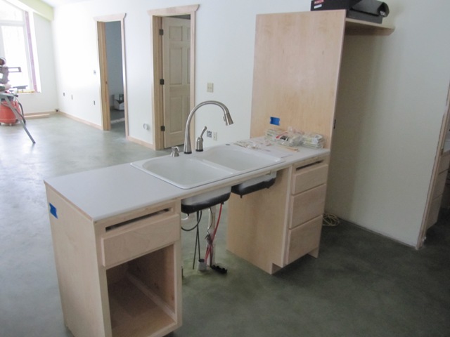
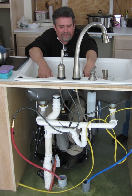
Jay’s brother Dave tested the kitchen sink for wheelchair accessibility. Soon all the plumbing will be enclosed.

February 22, 2010
Dan mounted the panel that encloses the bottom of the sink and the plumbing below, so it looks a lot more finished now.

March 17, 2010
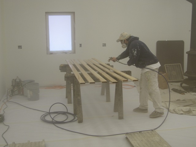
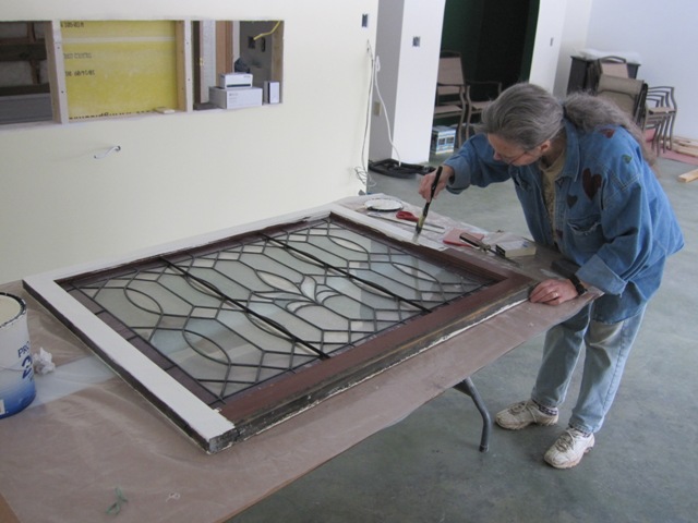
Bruce sanded the cherry tree out in the driveway, and then sprayed it with the same water-based lacquer that we used on all of the cabinets and trim.

March 18, 2010
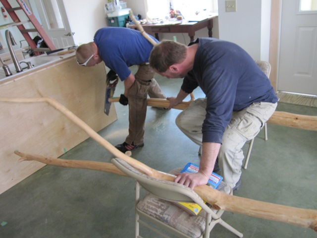
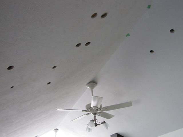
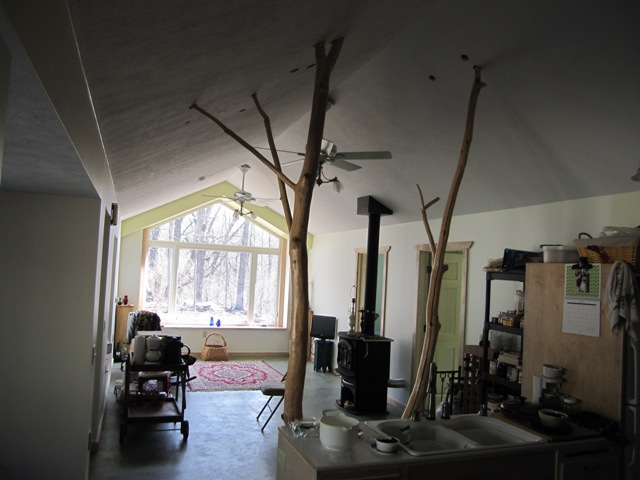
With the tree lacquered, we brought it into the cottage. We laid it up on chairs and aligned it with the room, then marked out on the floor where the ceiling would intersect the tree. Then we trimmed the branch ends so they will protrude just a little above the ceiling level. We also carefully measured the distance from the peak of the ceiling to each branch, so we could locate where we need to drill holes in the ceiling. We measured up from the floor to each branch tip, to find the horizontal offset from the back of the counter to each hole.

With the holes carefully marked out, Bruce drilled through the drywall. The fit was perfect, except that every hole location was off horizontally by exactly the height of a chair. Duh! So now we had to drill a new set of holes offset 16″ from the first set. That’s going to take a lot of drywall patching.

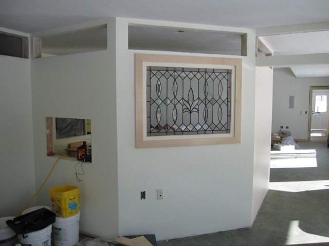
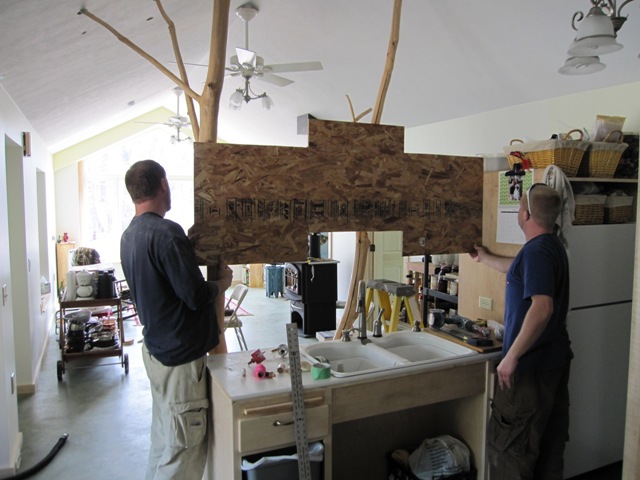
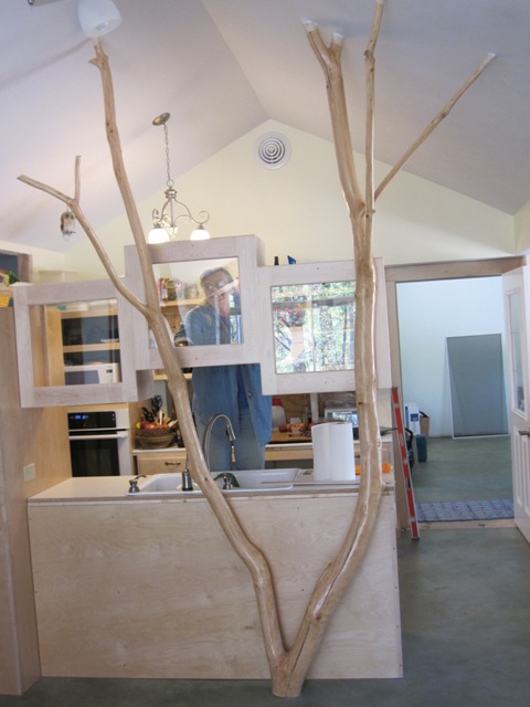
Jay, Nash and Bruce raised the tree into place, and it fit just right into the second set of holes we drilled. Bruce made a template of the cabinets that will mount to the tree so that we could check the fit. The right hand side of the cabinets will anchor to the refrigerator enclosure, and the left side will be supported by the tree. The cabinets will have glass doors and glass backs so they will let light through into the kitchen.

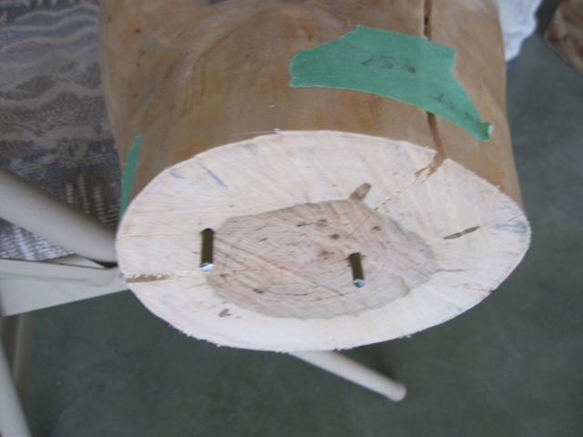
At the base of the tree, we drilled two small holes into the concrete, and pounded a couple of matching spikes into the wood. These will prevent the bottom of the tree from moving sideways.

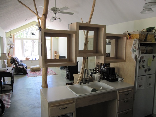
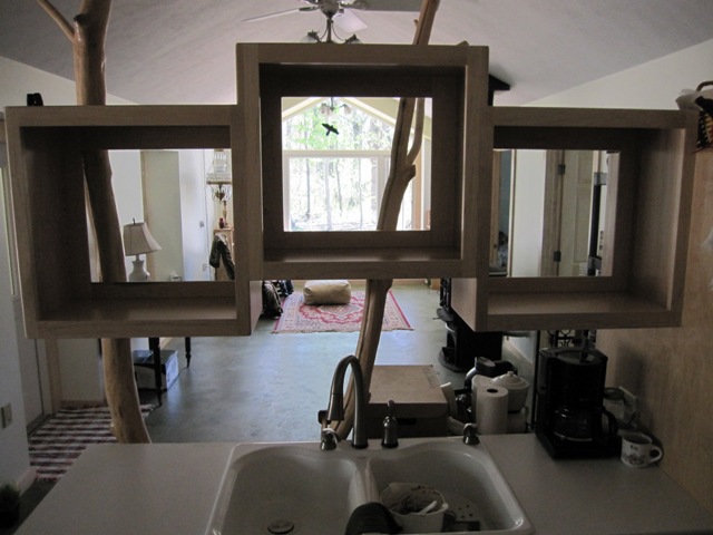
Here are two views of the tree in place, first looking south toward the living room and then looking north toward the kitchen. Fortunately the heavy branch on the right happened to align with a roof truss, so we anchored it to the truss with two heavy screws. The other smaller branches will be stabilized when we pack spackling around them to seal all the holes in the drywall.

April 26, 2010
With the floating cabinet finally finished, it was time to mount it to the tree in the cottage kitchen. When we installed the tree we managed to get the main limb very close to vertical, so it required only a small spacer at the top to match the vertical cabinet back. We secured the finished cabinet to the tree with two large screws and anchored it to the refrigerator cabinet on the other side.

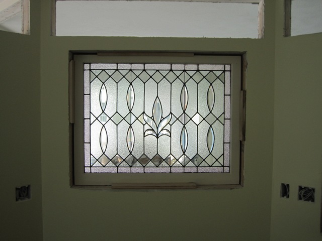
Here are two views of the floating cabinet from the kitchen side. The backs have built-in panels of 1/4-inch thick glass, and the fronts have doors (not installed yet) with similar glass panels. Each cabinet will also have an adjustable glass shelf.

Wall Insulation

November 13, 2009
The exterior walls of the house are double stud walls, with the outer stud wall resting on the concrete foundation and the inner stud wall resting on the heated floor slab. Here’s a photo showing the inside of the wall. At the top of the photo is the outer wall of the house, and you can see the concrete foundation underneath it. Next comes two 3-inch-thick layers of extruded foam insulation, which blocks heat loss from the heated floor slab to the cold outside. In this photo you can just see about 1/2″ of the heated floor slab between the foam and the inner stud wall at the bottom of the photo. As you can see there is a considerable gap between the two layers of pink foam, and there is a possibility of moisture moving up from the earth below into the wall cavity. To prevent moisture from reaching the cellulose insulation that will fill the wall, we decided to add a layer of spray-on foam into the bottom of all the double walls.

In order to prevent any overspray from getting on the concrete floor, and to protect the concrete floor from drywall mud that is coming soon, we put down red rosin paper over the floor. Thanks to help from Di we got most of the floors covered, but to save time we just covered the outer 3 feet in some areas. We’ll have to cover the rest before drywall but it’s enough to protect the floor from foam overspray.

We purchased a spray foam kit from Foam it Green, and it’s a two-part polyurethane foam that is shipped in two tanks weighing about 50 pounds apiece. It comes with 15′ hoses that connect the tanks to a gun handle, and the two components mix together in the spray tip as they are sprayed. This kit is said to yield about 600 board feet of foam, which would fill a wall cavity 12″ wide by 600′ long and 1″ deep. We don’t have that much wall so we should have some left for touch-up or for other hard-to-insulate spots in the house. The kit comes with a protective Tyvek suit, which is nice but not really necessary as it’s pretty easy to control the spray.

And here’s a movie of the foam being sprayed. The bluish light that appears where the foam is being sprayed is from an LED headlamp:

The foam solidifies and is dry to the touch in about a minute. Here’s how it looks afterward:

It did a good job of sealing around conduits that run down under the floor slab. In the second photo below you can see a minor problem – if you look closely you can see some of the pink extruded foam board showing where the spray missed. We’ll have to go back over and touch up some spots like this, but overall it worked pretty well and should keep the cellulose nice and dry.

November 18, 2009
The insulation crew started by stapling mesh to the insides of the double walls. The black mesh is a porous fabric that is used on the undersides of mattresses.

Once the mesh was stapled to the studs they commenced blowing cellulose into the wall cavities, first going under the upper mesh to blow the bottom, and then filing the top half through slits near the ceiling. The flash makes it look dustier than it was, but it was pretty dusty.

Solar Heat Collectors

We use six 4-foot by 10-foot Heliodyne Gobi flat plate collectors to heat water for space heating and domestic hot water. The heat from these panels is stored in a large storage tank and then used to heat water for showers and other fixtures, and to heat the water flowing through the radiant floors in the winter.

November 9, 2009
We mounted the six collector panels on the vertical wall above the south side of the garage. Liz, Bruce and Dan unloaded them from the trailer and lifted them up onto the roof above the front porch. Each panel weighs about 150 pounds so they’re manageable but not exactly lightweight. We set them on an aluminum rail bolted into the wall structure at the bottom, and then attached them to the wall with small clips on the sides. The panels come with union fittings at the top and bottom corners so we just screwed them together. The pipes running along the bottom connect to form a manifold into which the cold fluid flows from the left (west) end. The fluid then picks up heat as it flows upward through each panel, and the pipes running along the top form another manifold that sends all the hot fluid out the right (east) end. From there it goes directly to the storage tank and through a copper heat exchanger that transfers the heat to the water in the tank, then through a pump and back to the cold inlet. The fluid in this loop will be a mixture of water and non-toxic antifreeze so it won’t freeze on cold winter nights.

It only took us about 2 hours to mount all 6 panels. The hardest part was the heavy lifting, most of which was done by Dan and Bruce.

Even with the very weak sunshine today, the panels were already getting hot. After less than an hour in the weak sun, the copper fittings at the top were too hot to hold comfortably, perhaps 120 degrees F. The panels are designed to withstand “stagnation”, meaning sitting in full sun without any fluid flowing through them, but it will make them quite hot and rather than stress the panels we covered them with tarps for now. We will uncover them after the rest of the plumbing is connected and fluid is circulating through the panels.

December 29, 2009
Here’s a photo of the collectors finally in operation, on the first sunny day after we got the plumbing hooked up.

Windows

November 5, 2009
After a long wait, most of the windows finally arrived from Serious Windows. It took us a couple of hours to get them all sorted out and delivered to their respective areas of the house. Dan and Bruce installed the fiberglass casement windows in the entryway and bedrooms, and these went up fairly quickly. We are still waiting for some of the larger window units, as well as the nailing flanges that will let us install the vinyl windows in the workshop and porches.

November 6, 2009
With the kind assistance of the roofing crew, the large south window assembly of the cottage great room was lifted into place. The narrow windows on the right and left sides are openable casement windows, and the others are fixed. That way we can get a breeze without screens obscuring the center view.