Includes affiliate links that help offset our expenses at no cost to you.
This page shows photos of the plumbing system that transfers heat from the solar heat collectors to the heat storage tank. For a discussion of the technical design behind this system, click here.
December 21, 2009
Our plumber finished installing the plumbing for this system today.The first photo below shows the completed solar heat plumbing system, and the second photo is a side view showing the connections into the heat exchangers in the heat storage tank.
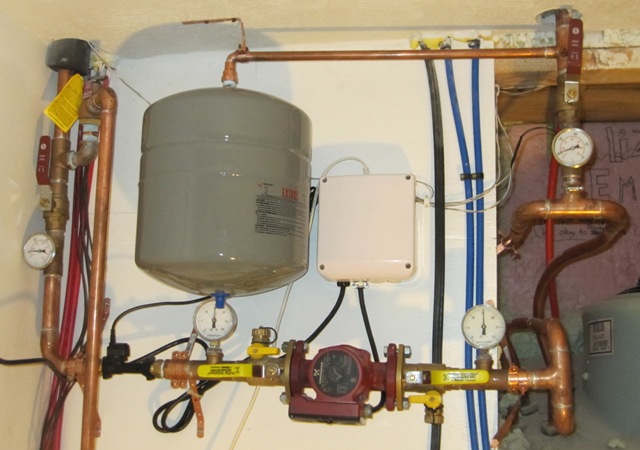
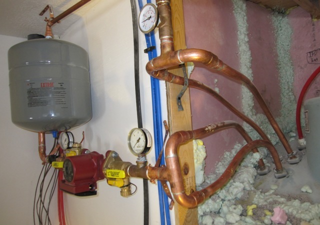
The fluid will flow clockwise in this photo, with the hot fluid from the top of the heat collectors coming down on the upper right. The flow splits in two and enters the tops of two of the heat exchanger coils. Each coil is a 100 foot length of 3/4″ diameter copper tubing, and the heated fluid spirals downward through the coils, then the cooled fluid comes up and out the two pipes on the bottom of the photo. Here the two parallel flows recombine and enter the pump, which circulates the fluid back up to the bottom of the heat collectors to be heated again by the sun.
December 23, 2009
After pressure testing the system it was time to clean it and prime it. The photo below shows the Wayne 1/2 HP Transfer Pump that we used to prime the system. The pump draws the fluid from the 30-gallon tub on the floor and pumps it into the solar loop. Once the loop is full the fluid starts running back out the outlet hose and back into the tub. The fluid looks really dark in this picture but it’s actually light pink.
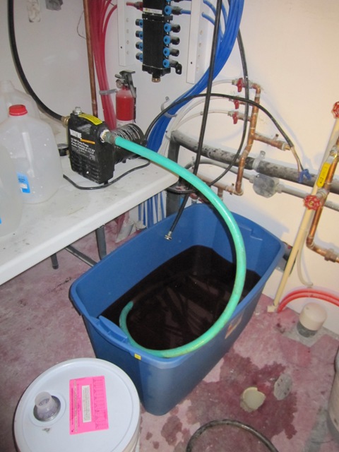
Here’s a photo of the connections for priming. The outlet of the transfer pump goes to the connection on the left hand side, and the return from the solar loop exits out the hose on the right hand side and returns to the tub. The valves next to the pump let us close it off, so we’re pushing the fluid through the system without using the circulation pump.

First we pumped in a solution of TSP-PF Cleaner, to clean out any solder flux or other residue from inside the pipes and solar collectors. Then we flushed the system with plain water, to rinse out all the TSP. Finally, we filled the system with a mixture of non-toxic propylene glycol antifreeze and water, running the pump’s outlet into a pail until it turned from clear (water) to pink (glycol). Then we put the outlet back into the fill tub and circulated the solution until it seemed that all the air was out.
Based on the manufacturer’s recommendation we chose a mixture of 60% glycol to 40% water, in order to give burst protection down to -40 degrees F. The fluid may freeze solid or slushy before it gets that cold, but it won’t expand and burst the pipes until it reaches -40. It’s never gotten that cold here but it has dipped down around -20 on occasion, so a 50% glycol solution would just barely offer enough protection. And the glycol’s freeze protection degrades over time, especially after it’s been hot, so we want an extra safety margin here. The down sides of using more glycol than necessary are somewhat higher cost and lower heat transfer efficiency, but these are not significant compared to the cost of bursting pipes inside the collectors.
The antifreeze contains additives designed to inhibit corrosion and to reduce scaling in the pipes, but it’s inadvisable to use very hard water. Our well water is pretty good but it does contain a fairly high level of calcium, so it’s not the best choice for this system because it would eventually cause some calcium deposits in the pipes. Instead we used bottled “purified drinking water” from the dollar store, which is purified by reverse osmosis and only cost $1 per gallon. We tested the hardness of it and it’s much softer than our well water so it should work better.
December 24, 2009
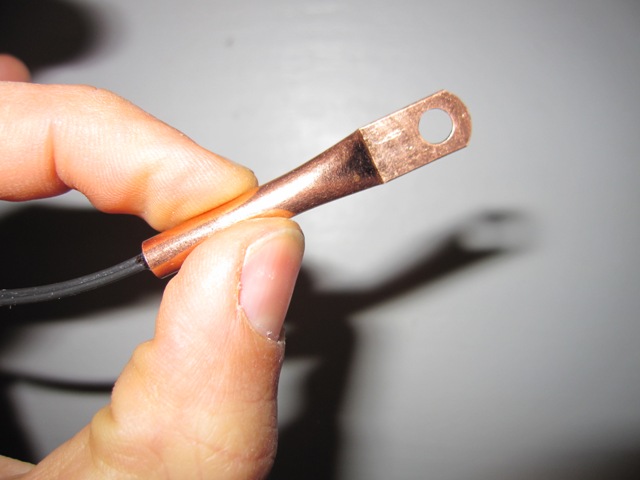
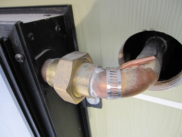
Today Jay wired up the Heliodyne Delta-T Pro controller that controls the pump. It uses temperature sensors to measure the fluid temperature at various points in the system. The first photo below shows one of the sensors, and the second photo shows one mounted on the outlet of the solar heat collectors. After mounting the sensor, the pipe was wrapped with thick foam insulation to reduce heat loss.
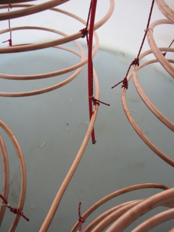
The controller also has heat sensors inside the heat storage tank, and these are simply slid down inside the red PEX tubes that were installed as the tank was built. The photo on the left shows the end of the upper heat sensor tube, and the one on the right shows the end of the lower heat sensor tube. These let the controller measure the temperatures at the top and bottom of the tank, so it can activate the pump when the collectors are warm enough to heat the water in the tank.

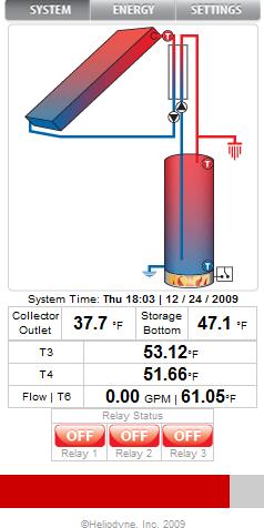
The controller has an Ethernet interface, through which it provides a simple browser-based interface to monitor and configure it. The display below was taken late in the day after the sun had gone down, so the collectors are a chilly 37.7 degrees. The bottom of the storage tank is at 47.1, and the top of the tank (T3) is at 53.1 degrees. This is, on average, the same temperature as our well water and the tank is essentially at the same temperature as when we filled it since we haven’t collected any solar heat yet. The other temperatures are measured at the heat exchanger inlet and outlet, and they will let the collector compute how much heat energy is actually being collected once we get some sun. This page will also display the actual flow rate through the system when the pump is running.
December 29, 2009
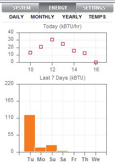
After a couple of days of weak or no sunshine, we finally got a sunny day! The first display below shows the system running, with a collector output of 76 degrees. The bottom of the storage tank is at 53 degrees and the top is about 63 degrees. The second display shows the energy graph for today, with a peak output of 30,000 BTU/hr around noon. That’s equivalent to about 10,000 watts! Our total harvest today was about 120,000 BTU according to the controller. The average tank temperature increased by about 8 degrees today, indicating a gain of about 134,000 BTU since it contains roughly 17,000 pounds of water at the moment. It’s not surprising that these BTU values are a little different, since the accuracy of the temperature sensors is only about +/- 1 degree, and the fact that they’re pretty close substantiates that we collected somewhere around 125,000 BTU of solar energy today. That sounds fantastic but it’s only enough to heat the house for 12 hours presently. We expect to cut the heat loss quite a bit more once the windows and doors are fully caulked and weatherstripped and the HRV is in operation.