Shed Addition

August 28, 2012
As we’ve expanded the gardens and vineyard we need space to store all our garden equipment, and also a dry place to store our firewood for the winter. So we decided to put a shed addition on the east side of the workshop, where it will be convenient to garden activities and also easily accessible from the shop. It’s going to be a simple structure, 24×14 feet with a deck-like floor and a sloping roof.

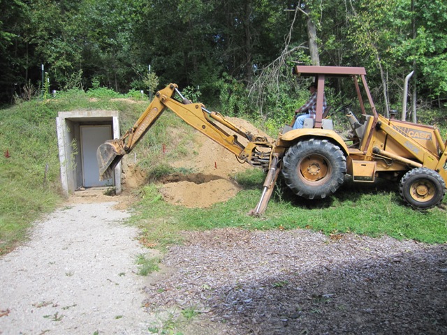
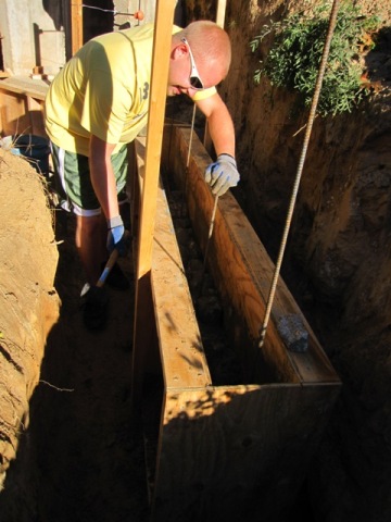
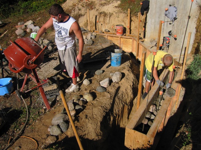
The first step was to dig holes for the four footings that will support the structure. The building inspector recommended that we design for additional weight due to the likelihood of snow drifting on the shallow roof, so the footings need to be pretty big. We rented a small backhoe to make the digging easier.

After a few hours Dan had all four holes dug to a depth of 42 inches as required.

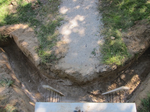
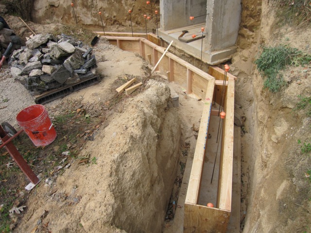
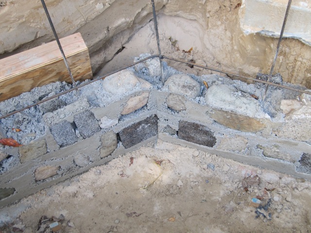
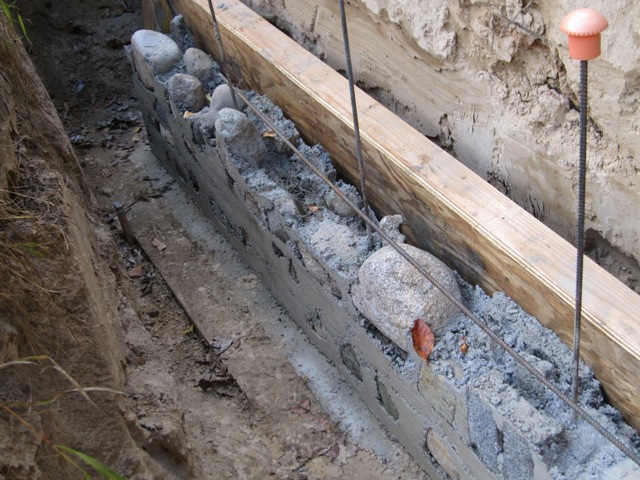
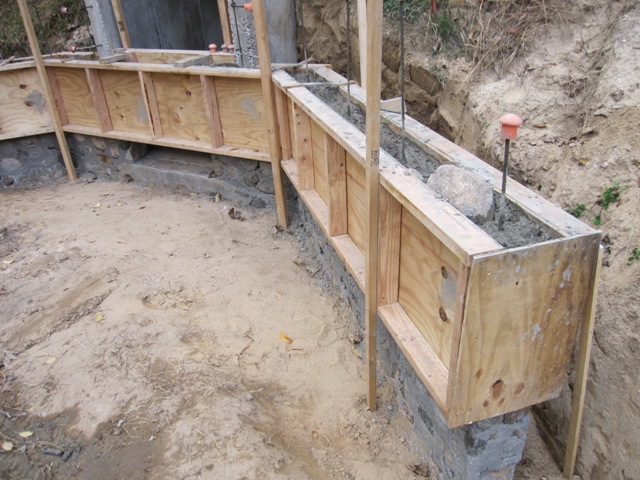
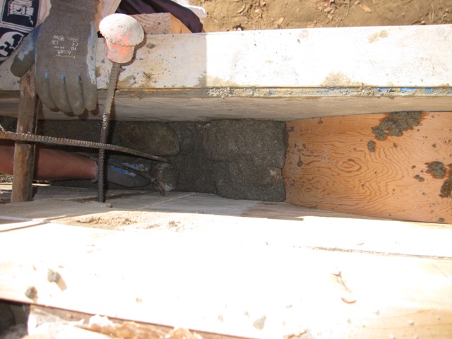
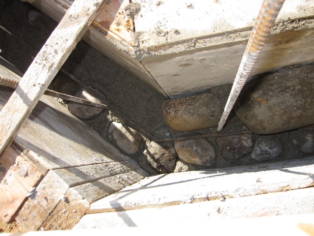
Into each footing hole goes a plywood form that’s about 29 inches square and 6 inches high. Strictly speaking we could meet code requirements with footings a few inches smaller, but making them a little bigger than required takes minimal extra time and concrete, and it will give us a little more leeway when positioning the posts.

September 4, 2012
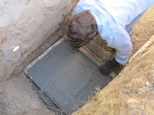
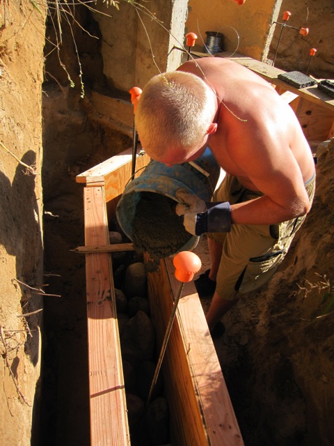
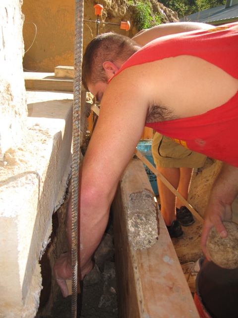
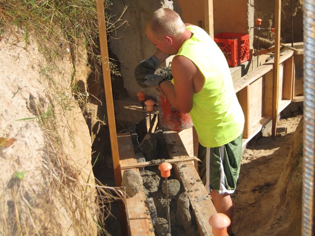
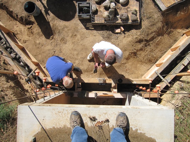
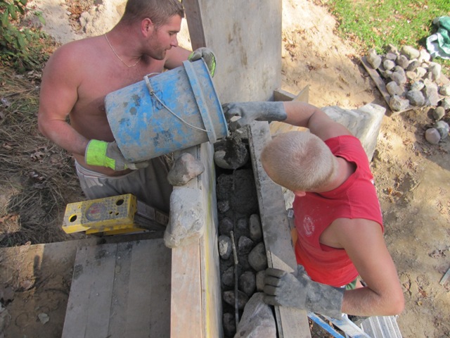
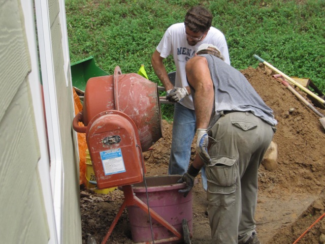
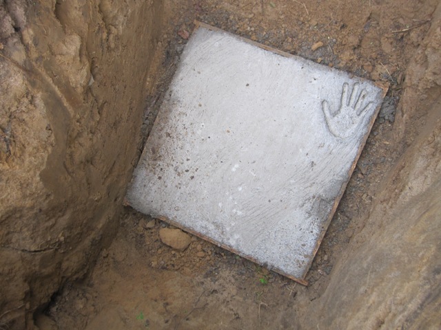
Jay and Dan mixed and poured the concrete for the footings.We used a basic bagged concrete mix, nothing special, and it took a total of 26 sixty-pound bags for the four footings.

By the next morning the concrete was set up well.

September 6, 2012
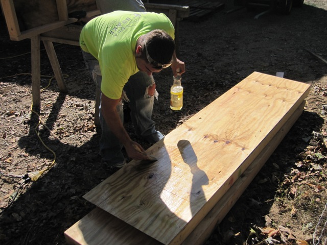
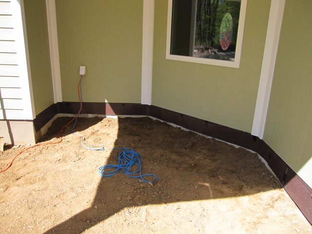
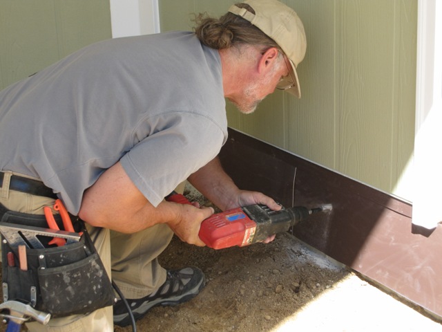
Dan drilled 1/2″ holes into the concrete stem wall of the shop, and attached a ledger with concrete anchors. Before attaching the ledger he liberally caulked behind it at the top, to prevent moisture and insects from migrating into the structure of the wall. All of the wood at or below floor level is pressure-treated.

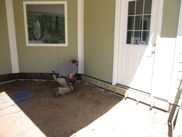
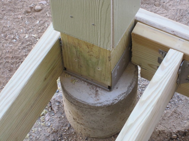
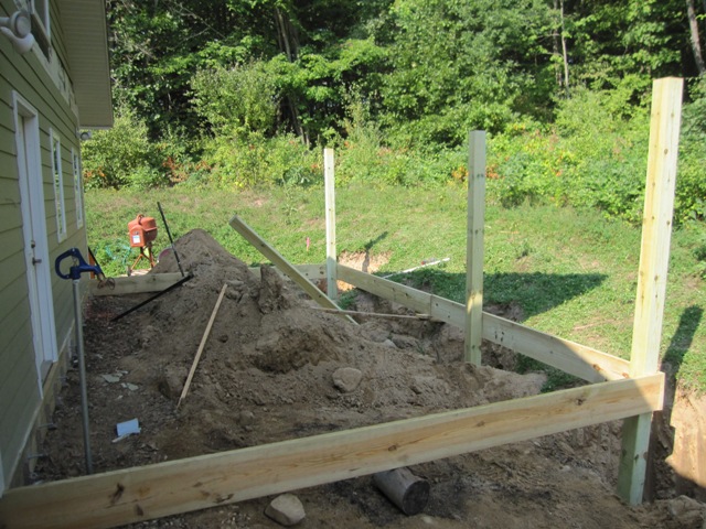
We stood up the posts on their footings, and temporarily attached a few floor joists and the beam in front using small screws, strong enough to hold the boards in place but allowing easy repositioning. We nudged the posts back and forth to get them plumb and to get the whole frame level and square.

September 7, 2012
After carefully marking out the cut lines, Dan cut the posts to length and notched them to receive the upper beam that will support the roof.

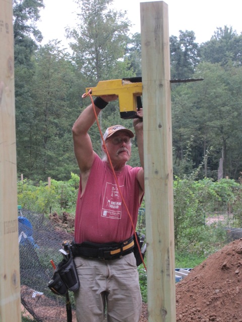
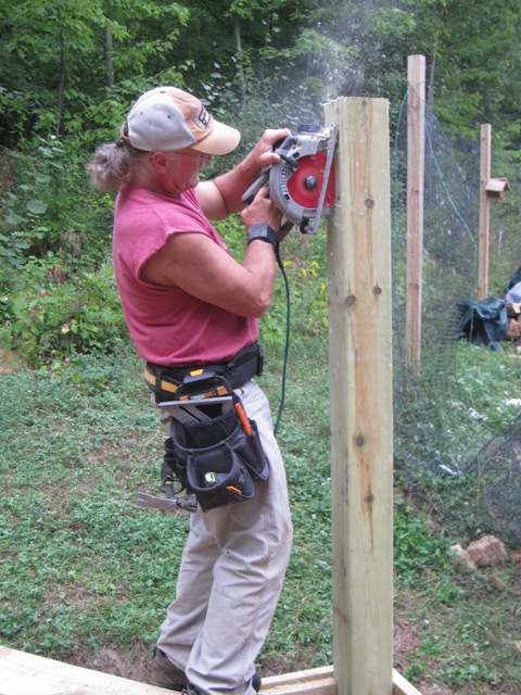
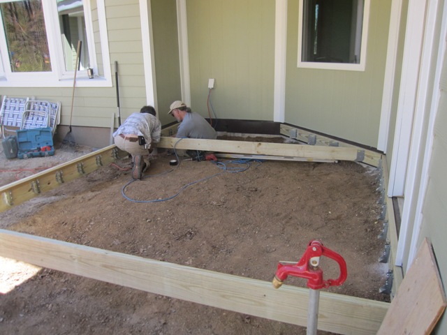
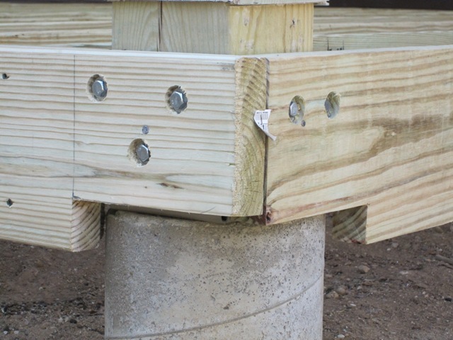
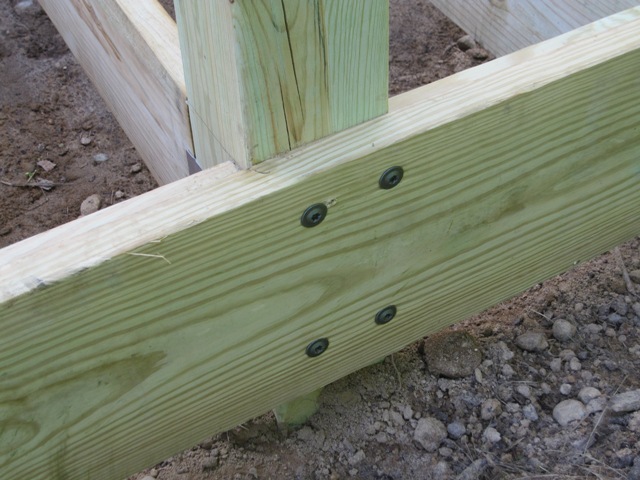
We set the upper beam, which is made from two 2×12’s, and tacked it up with small screws. Once it was all in place, we went back and readjusted the posts to get everything as level and square as possible. Then we anchored the beams solidly to the posts using heavy “power lag” construction screws that are rated for outdoor use on treated wood. The upper beam sits in notches in the posts so the screws just keep it in place and don’t support any weight, but the lower beam is directly supported by the lag screws shown in the second photo below. These screws will carry half the floor load so we used four 3/8″ lags in each post, which will put a maximum shear load of about 500 pounds on each screw and they should be plenty strong.

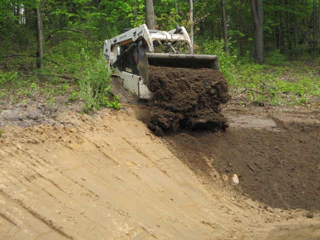
With the posts and beams solidly anchored together, we started backfilling the footing holes and tamping the sand down around the posts as we filled them. We filled the first one before removing the outside floor joist so the tractor could reach the next, and Dan kept checking the posts with a level to make sure we were keeping them plumb.

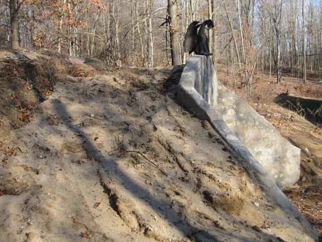
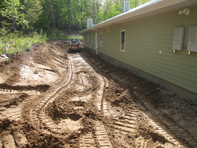
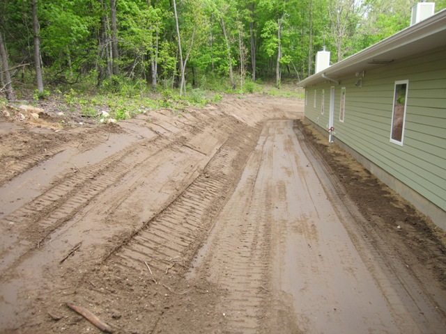
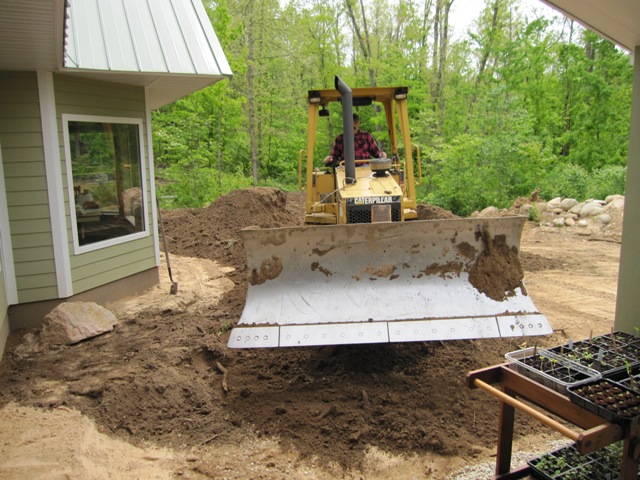
Once all the holes were filled, Jay graded the area so that water can drain away from the back of the house on the north side, under the shed on the east side, and down into the garden to the south. We don’t often get rain heavy enough to have surface water moving like this, but occasionally we get a downpour strong enough to create a small “river” so we want to make sure it’s directed away from the structure and won’t pool anywhere.

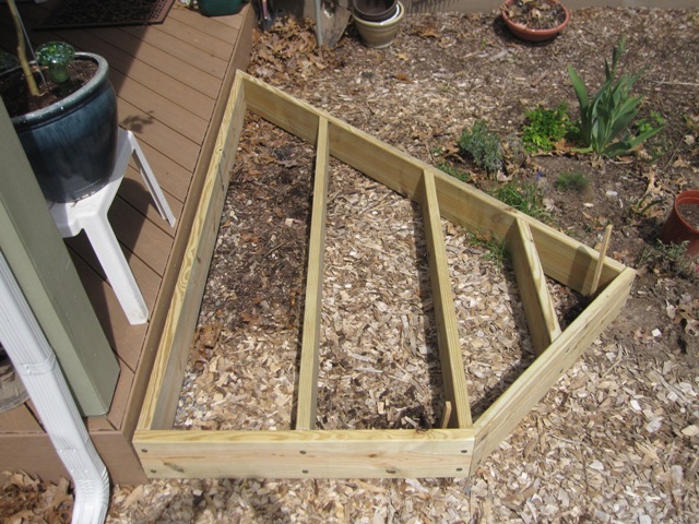
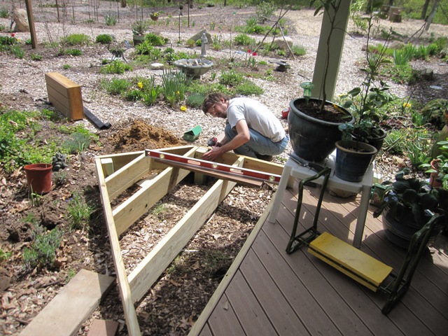
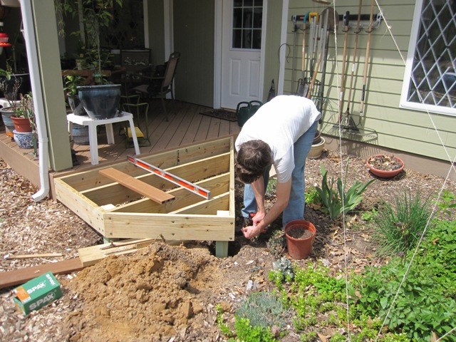
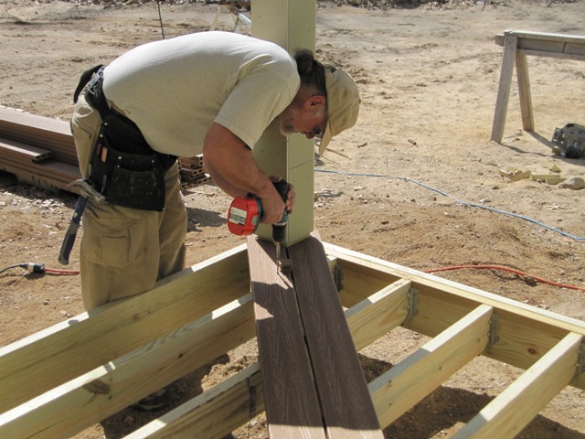
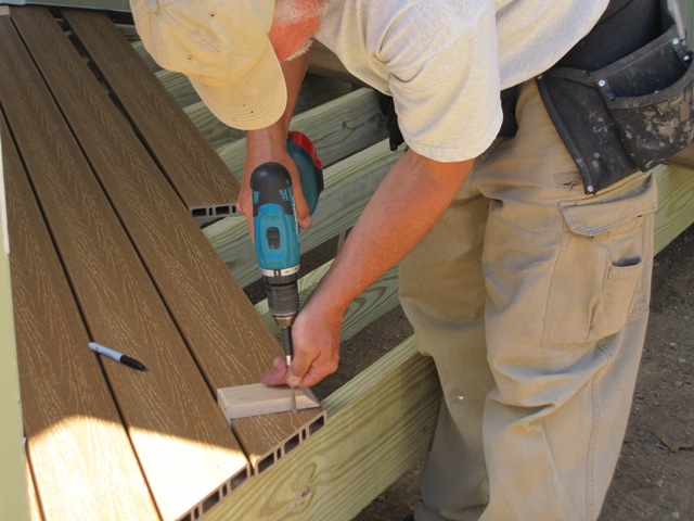
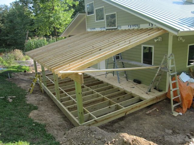
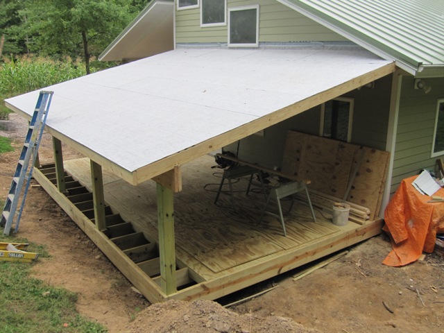
Once the filling and grading was done, Dan cut and fit the floor joists. They went up pretty fast, and it’s starting to look like a floor now. The blocking near the center of the joists keeps them from twisting, and it will also support one seam of the plywood floor. We’ll put in lighter-weight blocking where the other two seams will be, so the plywood will be supported on all edges. As you can see in the photos below, the outer frame members sit 3/4″ higher than the floor joists so the edges of the plywood will be covered on all sides.

September 11, 2012
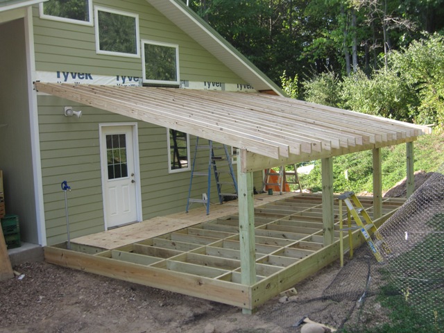
To support the roof Dan attached a ledger to the side of the house, anchoring it into the wall studs with heavy construction lag screws. Then he started cutting and fitting the rafters. The window above limits how high we can put the roof, and in order to maintain at least a 3/12 pitch the rafters get a bit low on the east side (to the right in these photos). In order to maximize the headroom we used 2×6 rafters spaced 12″ on center, which takes more rafters than if we’d used 2×8’s but it gives us 2 inches more headroom.

By the end of the day Dan had laid all the rafters in place and the roof had taken shape. Next we need to get them all securely anchored down and have the framing inspected before we can apply the floor and roof sheathing.

September 12, 2012
Dan attached the fascia to the front of the rafters, while Jay installed “hurricane straps” as required by code to anchor the roof to the wall.

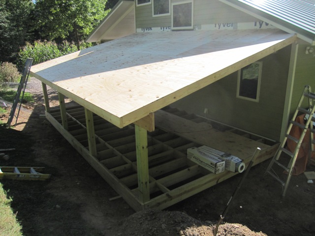
Then we moved on to the roof. Dan nailed on the sheathing and it went up pretty fast.

September 13, 2012
We used a peel-and-stick roof underlayment that’s meant for use under metal roofing. It has a white non-skid coating so that it’s relatively safe to walk on, and it sheds water so it will work as a waterproof roof temporarily until the metal roofing is installed.

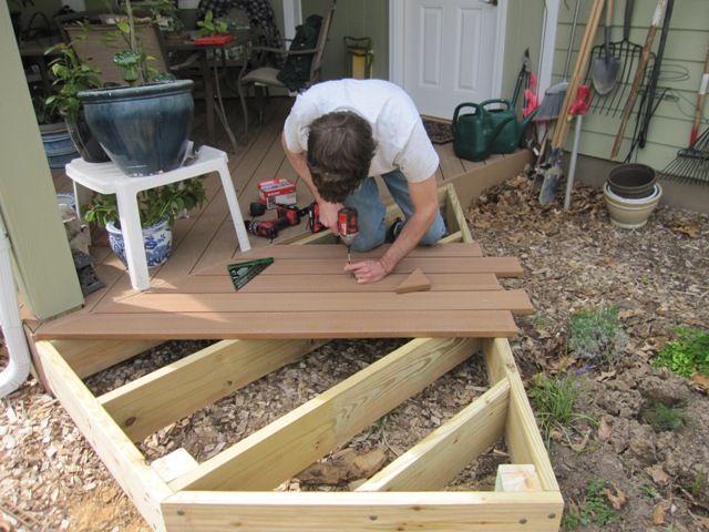
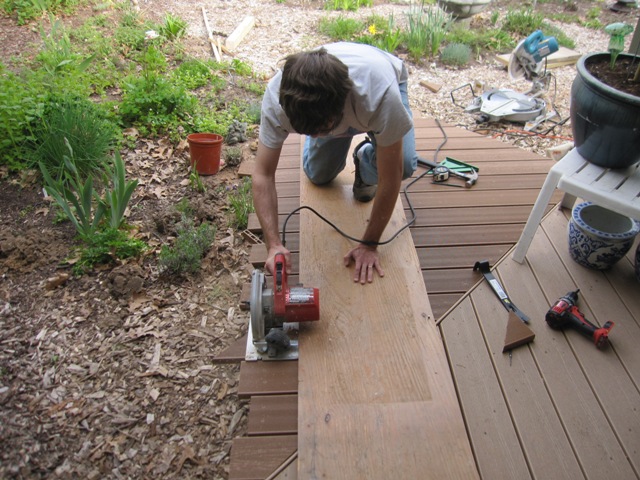
Dan started working on the floor, screwing down the treated 3/4″ plywood to the floor joists and blocking.

Around the bottom Dan attached some of the fencing material that we had left over from the deer fence, to prevent animals from crawling under the floor. The bottom edge is buried under the dirt and flared outward so it will be relatively difficult for anything to dig under it.

October 1, 2012
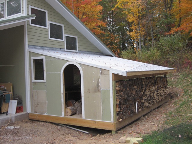
After Dan finished the floor and added the front wall and doorway, we stacked our firewood along the east side where it should get enough airflow to dry well. Once the wall was in place and covered with plywood sheathing, it was fairly dark inside so we decided to add a window to let more light in.

Dan framed in an opening to fit a window that we had salvaged from an old storm door, and boxed it in with fiber cement trim board to match the rest of the house. This makes it a lot lighter inside the shed.

October 2, 2012
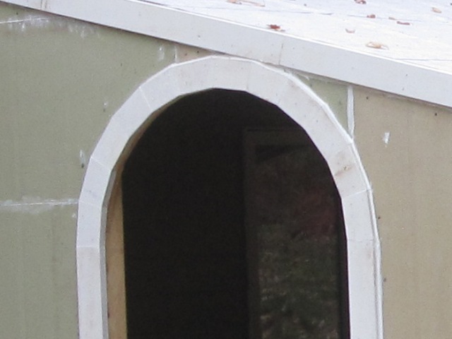
Dan finished up the trim and siding today. He pieced together some leftover pieces of fiber cement siding board so it looks a bit odd but once it is painted it should look seamless and match the rest of the house. He had to cut and fit 12 trapezoidal segments of 1×3″ fiber cement trim board to make the arch. We’re still waiting for the roofers to come install the metal roofing so the “roof” is still just the peel-and-stick underlayment but it’s rated for a few months of exposure and it should hold up until it’s covered with metal.

October 4, 2012
The roofers installed the metal roofing today. It went up pretty fast except for the corner where it meets the soffit of the shop roof, which required some cutting and fitting.

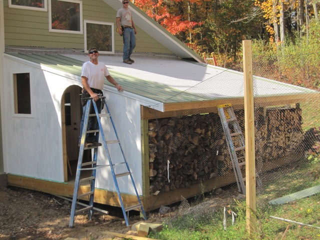
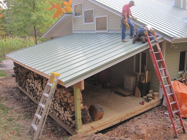
While the roofers were roofing, Jay primed and painted the front wall. It’s pretty much finished now except for some flashing on the fascia and beam, and replacing the last row of siding above the roof.

Cooling System, Enhanced

July 15, 2012
We installed our original cooling system in July 2010 and it has worked reasonably well, but over the last few weeks we’ve had a hot spell with daytime temperatures mostly in the upper 90’s and well over 100 degrees Fahrenheit for a few days. That’s normal in some parts of the world but in Michigan, we consider that HOT! Over two weeks of unusually hot weather the house reached 77 degrees at the warmest point when it was 105 outside, which is actually pretty good since we’re cooling the entire house for about 30 cents per day, but 77 degrees inside is a bit warmer than we would like and we anticipate more hot weather to come. The original cooling system circulated water through the radiant floor slabs and through a copper coil heat exchanger in one half of the cistern, so we decided to add a second heat exchanger in the other half of the cistern in order to increase the capacity of the system, both in terms of power (BTU/hour) and total heat capacity (BTU).

The first order of business was to improve the plumbing in the mechanical room. Previously I just connected the cistern loop with hoses connected to the drain and fill valves of the hydronic heating (now cooling) plumbing. This connection worked okay but it was only meant to be temporary and probably restricted the flow rate somewhat as the water had to flow through the drain/fill valves. So, I disassembled the copper piping and added two T fittings for direct connections to the cistern cooling loop. I also relocated one of the temperature gauges so that I can directly measure the temperature of the water returning from the floor slabs. This will permit a more accurate measurement of the system’s performance. The photos below show the plumbing before and after this change. The vertical red 5/8″ PEX tubing runs to the heat exchangers in the cistern. Water returns from the floor slabs through the manifold at the very bottom of the photo, then flows up through the temperature gauge and then out the lower T fitting and down to the cistern. It returns through the long red tube that’s visible in the photo, into the upper T fitting and then up and around to the circulator pumps and back out to the floors through the upper manifold. This is essentially the same as it was before except that it’s now a permanent connection, with the temperature gauge moved down to the warm side of the loop so I can directly measure the temperature drop across the heat exchangers. In the winter we’ll close the two valves to the cistern lines and open the one in the middle, so the heating water won’t flow through the cistern loop.

After the plumbing in the mechanical room was redone, I opened up the cistern to add a second heat exchanger. This was the first time we had opened it in about 2 years, so it afforded a good opportunity to examine the clarity of the water. Since we’ve had a hot, dry spell for the last 4 weeks we have been using a lot of cistern water for the gardens, and we’re down to about 36 inches or 4,300 gallons, out of a total capacity of 12,000 gallons. Hopefully we’ll get some significant rain soon to replenish our irrigation water supply, but we can refill it from the well if necessary.

The first photo below shows the first (north) half of the cistern where the rainwater enters through the white pipe in the lower left of the photo. The copper coil is the heat exchanger that I installed 2 years ago for the original cooling system. The camera’s flash exaggerates the small amount of material floating on the surface, some of which fell down when I opened the hatch. You can see that the bottom is covered in dark sediment, which is not surprising since this side receives water from the roof. I didn’t climb down far enough to measure the sediment but it appears to be less than 1/8 inch thick. This will have to be cleaned out someday, but probably not for quite a few years. The second photo shows the new heat exchanger coil in the second (south) half of the cistern. It’s quite striking how much cleaner the water is on this side, because most of the sediment settles out on the first side before water flows by gravity through the floating filter (visible at the upper left of the first photo) and into the second side. We pump water out through another floating filter (not visible) in the second side where the water is cleanest. There is a 5-micron filter attached to the cistern pump in the mechanical room, and after nearly 3 years of operation we still haven’t needed to change the filter cartridge because there is almost no sediment in the water coming from the second half of the cistern.

The two heat exchanger coils are connected in parallel through T fittings as shown in the photo below, so that the water splits and flows through both of them together rather than flowing first through one and then the other. This will transfer approximately the same amount of heat into both halves of the cistern, and more importantly it should offer considerably less flow resistance than if they were connected in series so we should get a higher flow rate using the same amount of energy to run the pumps as before.

In the first post on our cooling system about 2 years ago, I reported that the system had a flow rate of 1.8 gallons per minute on the low-speed pump setting, and had a 5 degree temperature drop through the single heat exchanger in the cistern. That gave us an Energy Efficiency Rating (EER) of34, which is about 3 times as efficient as a good air conditioning system. After improving the plumbing in the mechanical room and adding the second heat exchanger, I measured a flow rate of 2.6 gallons per minute on the same low-speed pump setting and a 6-degree temperature drop. This increases our efficiency by 73% for an EER of about 60, which is 5 times as efficient as a good air conditioner. Using only 120 watts of electricity to run the pumps, the system is removing about 2300 watts of heat energy from the house. It can’t sustain this rate indefinitely because the cistern water will warm up until it reaches equilibrium with the rate of heat transfer into the earth through the cistern floor and walls, so I expect the efficiency to drop a little over the next week or two. But it’s still many times more efficient than the best available air conditioning systems and heat pumps. Its total cooling capacity is very small however, so it is practical only because our total cooling load is very small due to the extreme level of insulation in the house, because our south-facing windows have carefully designed overhangs that block direct sun in mid summer, and because we use very efficient appliances that add very little additional heat to the house.

Deck Ramp

April 29, 2012
When we built the deck 2 years ago we had planned to add a ramp to make it more accessible, and we’re finally getting around to building it. The ramp will attach to a landing that extends off the east side of the deck so the first step was to build the landing. It’s a simple structure that will be attached to the deck and supported by two posts. After marking the post locations Jay dug the post holes.

Once the posts were in place, Jay leveled the ramp and screwed it to the deck and posts with heavy-duty anchor screws that are rated for outdoor use with treated lumber.

After the landing was secured in place, Jay attached the decking and then trimmed the ends flush.

The photos below show the finished landing and the step, which just sits on the ground in front of the landing. The ramp will attach to the front face.

May 6, 2012
The ramp is made of treated 2×6’s and is ten feet long by three feet wide. Rather than cutting the 2×6’s at the far end, Jay just dug a trench for them so that the end of the ramp will be at ground level.

Here’s the finished ramp with the decking attached. The side rails are made of solid 1×6 composite decking and they extend above the deck surface to prevent wheels from rolling off the sides of the ramp. This works well for a wheelchair and garden carts too.

Appliance Garages

March 4, 2011
The first photo below shows the cottage kitchen wall way back when it was first painted, where you can see the deep boxes that we set into the exterior wall to the right and left of where the cooktop will go. These boxes are about 12 inches deep, and the second photo shows how they look now that they are finished, as the tambour doors slide up to provide storage for small appliances.

It would have been convenient to put electrical outlets inside the garages so that we could leave appliances plugged in and just slide them back for storage. But this could pose a fire hazard if an appliance were to be accidentally left turned on while inside the garage. Therefore we decided to put electrical outlets only outside the garages, right above the doors as shown below. This is a bit less convenient but it ensures that we can’t put an appliance away while it’s still plugged in.

Here’s how the main kitchen looked right after the drywall was painted. Whereas the cottage kitchen’s appliance garages were set into an exterior wall that was 16″ thick, the main kitchen’s walls adjoin other rooms in the main house so we simply left holes in the wall as shown below.

Here’s a view of the finished west wall of the main kitchen, with the appliance garage door open and closed. It’s 30 inches wide and 16 inches deep so it’s big enough to hold several small appliances, and with the door closed it makes things a lot less cluttered.

On the north wall of the kitchen is the cooktop with an appliance garage on either side. These are only 12 inches deep but still large enough to store quite a bit.

The cottage kitchen’s 12-inch-deep appliance garages were set into an exterior wall that is 16 inches thick so they are hidden, but the main kitchen’s wall adjoins other rooms so the plywood enclosures protrude through the wall into those rooms. These will be surrounded by cabinets so they won’t be visible once the cabinets are in place. Until then, they make rather quirky shelves. At least they’re better than open holes in the walls, especially in the bathroom!

Root Cellar Retaining Wall

Our root cellar is built into the side of the hill behind the house, and it needs a retaining wall in front to hold back the earth that covers it. We’re going to use the slipform technique to build this wall, and here’s a sketch showing the wall’s design. The gray part will be underground, with footings that go down 46″ to get below the frost line, and the part above will hold back the earth behind it. The wings extend out at a 45-degree angle from the center section.

September 10, 2010
We hired a backhoe to dig a trench for the footings and the second photo shows the view from above, while standing atop the root cellar entrance.


September 14, 2010
We placed footing forms into the trench and leveled them, and had a commercial cement truck deliver concrete to fill the forms.

Fortunately we had watched the concrete crew pouring all the footings for the house last year, so we knew how it’s done. Jay screeded off the concrete level with the forms and then inserted lengths of rebar into the wet concrete. These rebar dowels will anchor the wall to the footings so it can’t shift. The sharp ends of the rebar would be very hazardous if someone were to fall into the trench, so we applied the orange caps over the ends.

Here are two views of the finished footings from the side and from above.

September 24, 2010
Our nephew Nash and his buddy Ryan have been busy moving and washing rocks from the rock piles in the woods nearby. They also hauled out some chunks of broken concrete (in the lower right pile) that we’ll use for the part of the wall that’s underground where it won’t show. This is about half as much rock as we’ll need, and enough to get started building the wall.

September 27, 2010
Nash and Ryan built the forms for the walls and brushed them with soybean oil before assembling them. Later we discovered that the oil isn’t really necessary since we willremove the forms each day before it has time to really adhere to the plywood. They assembled the forms so that the space between them is 8 inches, which will be the thickness of the wall.

Here’s a photo of the completed forms resting on the footings, ready for the first layer of concrete and rocks.

September 29, 2010
Nash and Ryan spent all morning mixing concrete and using it to pack rocks into the forms. We decided to use Quickrete 5000 because it develops strength quickly, has a high cement content so it should bond well to the rocks, works well in cold-weather applications, and (largely) because it was on sale. As you can see from the photos it’s not cold today but we’re expecting cold fall weather soon so it’s good to have a mix that will perform well in cold weather.

After laying about one foot of wall, we bent and inserted #3 (3/8″ diameter) rebar into the form. We’ll place horizontal rebar every foot and vertical rebar every 2 feet throughout the whole wall. It would be somewhat stronger with heavier #4 (1/2″ diameter) rebar, but we had a lot of #3 rebar on hand because we ordered extra back when they poured the radiant floor slabs for the house, and this should be plenty strong for this wall because it’s supported by its own angled shape and anchored to the front of the root cellar.

After the rebar was laid in place, Nash and Ryan added more concrete and rocks for a total height of about 18 inches. At that point we ran out of concrete, having used up twenty 80-pound bags. The wall is approximately 50% stone and 50% concrete, which seems to be typical for slipform stone walls. It would be possible to use less concrete by taking more time to find rocks and fitting them together very carefully, but the main advantage of the slipform technique is that it can be done fairly quickly. Besides, we want this to look like a root cellar that’s been here for a hundred years so we’re not trying for the appearance of fine masonry. It should look pretty good though.

September 30, 2010
Removing the forms revealed the prior day’s work. This part of the wall will be buried underground so we’re using it to practice the technique before making the visible parts above. Overall it looks pretty good, with some voids as expected but it’s a solid structure. We’ll mix the concrete a bit wetter from now on, to make it flow around the rocks better.

Now the forms are “slipped” up the wall, giving the technique its name. We supported them on 2×3 stilts screwed to the sides of the forms and this worked well.

October 1, 2010
Ryan and Nash traded off mixing concrete and placing it along with stones into the forms. In the second photo below you can see Nash pounding on the sides of the mold with a rubber mallet, which settles the concrete and stones and helps to release trapped air.

October 5, 2010
Today they placed the third layer, which is the first layer that will be visible above ground. The trench is mostly filled in now, so it’s much easier to get to the wall since they don’t have to climb down into a trench. The forms create a 36-inch-wide gap in the wall where the doorway will be.

They placed concrete and stones until about 2:30 PM, and it needs to cure for about 5 hours before the forms can be removed. We must remove the forms later today, ideally around 7:30 PM, when the concrete is just strong enough to hold together but still soft enough that it’s easy to chip and scrape it off the faces of the stones.

October 6, 2010
Last nightJay removed the forms and cleaned the concrete off the faces of the rocks, and today Nash and Ryan “slipped” the forms up the wall and placed the next layer of rocks and concrete.

October 7, 2010
Yesterday’s concrete was placed by 4:00 PM, so Jay waited until 9:00 PM last night to remove the forms and clean off the faces of the rocks. Waiting about 5 hours seems just right, as the concrete is firm enough to hold together but still soft enough that it’s easily chipped off the faces of the rocks. Any less time and it would be too fragile, and by the next morning it’s already too hard to clean easily. Jay brushed the surface with a wire brush to give it a weathered appearance, and here’s how it looked the following morning. The new concrete is darker in color because it’s still damp, but it will blend in as it dries. Eventually we’ll need to fill in the voids around some of the rocks with mortar.

Nash and Ryan back-filled behind the wall with sand, so that there’s no longer a trench and they’ll be able to walk up behind the wall to place tomorrow’s concrete and stones. They didn’t place any new concrete today, but spent most of the morning getting more stones from our stone pile back in the woods and cleaning them so we can use them in the wall tomorrow.

October 8, 2010
The next layer went in fairly smoothly and the wall continues to grow upward at about 18″ per day.

October 10, 2010
We set the slope of the outer segments using strings stretched from the end of the wall up to the beam set across the opening. You can see the yellow string on the left side of the second photo below. We’re not trying to make it perfectly straight, just close to the nominal slope. The sloped top of the wall is covered in “cap stones” that are relatively flat and thin, to provide a solid top surface that will resist the elements.


October 14, 2010
They got an early start on the wall today and finished it up by mid-day, so we could strip the forms and brush down the wall by late afternoon. It’s working well to wait 5 hours after placing the concrete before stripping the forms and cleaning the surface. The concrete is set up well enough to be stable but it’s still soft enough that it’s easy to scrape off the surface of the rocks with a masonry hammer, and the wire brush cleans off the smooth surface leaving a weathered texture.

October 15, 2010
In order to form the arch over the doorway, we picked out stones with a slight wedge shape and arranged them around a template of the 36-inch-wide arch. It was a challenge to find stones that were just the right shape, since we decided not to try splitting them. The second photo shows the form that will support the arch as we place the concrete. Jay made it using 8-inch lengths of 2×4 screwed to the back form. He cut saw kerfs into a piece of 1/4-inch plywood so it could bend around the arch, much like the form he made for the sitting counter.

We placed a shallow layer of concrete and stones into the forms and then laid in horizontal rebar to tie it together. In the first photo below you can see the stones just starting to cover the plywood arch form on the right. The second photo shows the rebar as it bends around the corner in the wall.

The first photo below shows the overall wall, and if you look closely you can see that we extended the center form up a bit more with plywood. The second photo shows how this supports the arch stones in front. We wanted to get plenty of concrete over the arch today so it will be strong enough to hold together when we remove the forms. You can also see some of the rebar that goes over the arch, and there’s another rebar length below it that is already cemented into the arch.

October 16, 2010
Late last night (when it was too dark for good photos), Jay removed the forms from the front of the wall and cleaned the concrete off the faces of the stones. He left the arch support in place so that the concrete could develop more strength before the support is removed. Here’s how it looks in the morning. In the second photo you can see some gaps under some of the stones and these gaps will be filled in with grout later. It looks like some of the stones might fall right out but they’re actually very well cemented in place.

By this time the new concrete was quite hard and we had no worries about removing the support from the arch. The first photo below shows how it looked under the archway right after removing the form. The concrete is quite smooth underneath and the surface texture doesn’t blend in with the rest. Fortunately it was still soft enough to brush off the surface layer and to chip away some of the concrete from the faces of the stones, and the second photo shows the result. We had hoped to expose a bit more stone but by now the concrete was too hard, and most of our arch stones didn’t have a very flat face on the bottom to show under the arch.

Here’s an overall view of the wall after using a pressure washer to clean the concrete drips off the faces of the stones. The wall will extend about 2 feet above the top of the root cellar entrance, and we should be able to place the rest of the concrete and stones in one more day.

October 18, 2010
We set a form in back of the wall, atop the root cellar entrance. The yellow line marks the curve where the top of the wall will go.

Ryan and Nash placed the remaining concrete and stones up to the curve marked on the form.

October 19, 2010
Late last night Jay removed the front forms and brushed down the surface of the wall. The stones looked good but alas the shape just didn’t look right, too pointed on top, and a little bit lop-sided. It was too dark for a good photo but looking back at the yellow curve in the first photo from yesterday, you can see that the curve doesn’t really blend smoothly from the sides up over the top. So Jay knocked out some of the stones while the concrete was still soft, and today’s project will be to fix the top so that the curve looks better.

To make a better shape, Ryan and Nash held a thin wooden spline over the sides so that it arched smoothly over the top. Then Jay marked the new curve on the form with red spray paint.

Once the new concrete was placed to fix the top arch, Nash and Ryan grouted the voids in the wall’s surface using Quikrete sand/topping mix, which is similar to the concrete that forms the wall but has no coarse aggregate (stones) just cement and sand. A regular masonry mortar mix would have worked but the color wouldn’t blend in as well with the other concrete.

Since it only took a little concrete and stones to fix the top arch, they had it placed by late morning so the forms could be removed by late afternoon. The first photo below shows the result, a much smoother arch than before. The top layers of concrete are darker because they are still damp, and will blend in with the others as they dry. The second photo shows a side view of the wall and entryway. This area will get back-filled with sand so that the entryway is completely covered with about 2 feet of earth over it.

November 29, 2010
After the back-filling was completed, the final touches were to mount our gargoyle to stand guard over the entrance, and to add a rustic wooden door to the front. The steel door inside the entry is secure and rodent-resistant, while this wooden door is mostly for looks and to keep leaves and snow from drifting into the entryway. Jay made it from some old barn boards so it would have a nice weathered look.

The back-fill is just sand, which won’t hold the slope very well but should be sufficient for the winter. Next spring we’ll top it off with topsoil to bring it up to the same level as the area behind and then we’ll plant a groundcover to keep the slope from eroding.

Cooling System

July 26, 2010
Through most of July we did fairly well keeping the house cool by opening windows at night and closing them up during the day. As long as we could get night-time cooling, the house stayed pretty comfortable even through some very hot weather, due the thermal mass in the floor slab and the super-insulated shell, plus overhangs over the south-facing windows to keep out direct sunlight in the summer. And then allergy season struck with a vengeance! Because our ventilation system has a very high efficiency filter on the air intake, we can keep the indoor air quality quite high and levels of pollen low by keeping the house closed up and running the ventilation system for fresh air. But unfortunately this is at odds with opening all the windows at night to cool down the house – we had to choose between keeping the air clean or keeping the house cool. So we decided to build a cooling system.

A typical whole-house central air conditioner has the capacity to remove anywhere from 3 to 20 kilowatts of heat from a house, and it consumes from 1 to 7 kilowatts of electrical power to do so. So even the smallest whole-house air conditioner takes about 1000 watts of electrical power to operate, and if it runs an average of 8 hours per day it will consume 8 kilowatt-hours of electricity per day. That’s approximately what we have been consuming to run the entire house, so adding a small whole-house air conditioner would double our energy consumption! Because of our extreme level of insulation and other strategies to avoid unwanted heat gain, we could probably get by with just a window-size air conditioner but even that would add at least 50% to our energy consumption. Fortunately, we have a better alternative.

Our cistern contains about 12,000 gallons of rainwater that we have collected, and counting the mass of the cistern’s concrete walls and floor that’s roughly 100,000 pounds of thermal mass. It is currently at a nice cool temperature of 64 degrees F. It has not only a lot of mass, but also a lot of surface area in contact with the earth 10 feet below ground level so it should remain cool even if we add some heat to it. This is a perfect place to dump unwanted heat from the house; all we need is a way to transfer heat from the house into the cistern.

To make a cooling system, we ran two lengths of 5/8″ PEX tubing from the mechanical room to the cistern. At the cistern they are connected to a 60-foot coil of 1/2″ copper tubing. The junctions use soldered-on connectors that join the PEX to the copper.

The heat exchanger coil is placed in the bottom of the cistern where the water is coolest. The water is actually quite clean, but it has some dust floating on the surface that makes it look dirty in the photo below. You can see the copper coil under 8 feet of water. It would probably work a little better to stretch it out more, so it could spread heat over a larger volume of water, but there isn’t much we can do about that without going for a swim.

Once the coil was in place, the other ends of the PEX tubing were connected to the fill/drain hose connections in the hydronic heating (now cooling) system. When the hydronic pumps are running the water circulates down through this heat exchanger in the cistern and then out through the loops in the floor slabs.

We started the system up and let it run for about an hour to stabilize, and then made some measurements to see how it was working. The two pumps are circulating about 2.2 gallons of water per minute on their “medium” speed setting. Water coming out of the floor slabs is at 72 degrees F, which is about the same as the surface temperature of the floors. After it circulates down through the copper coil in the cistern it’s coming back at 65 degrees, a 7 degree temperature drop. This lets us calculate how much heat we’re transferring out of the house and into the cistern: about 7700 BTU/hr or 2,200 watts. This is equivalent to a small window air conditioner, and less than even a small whole-house air conditioning unit if it were running all the time. But we don’t need much cooling capacity because the house doesn’t gain much heat, so it should be enough to keep it cool. We’ll need to run it for a few weeks to see how well it performs in hot weather.

Air conditioning units are given an Energy Efficiency Rating (EER), a number that indicates how efficiently they transfer heat out of a building. The EER is equal to the heat removed in BTU/hr divided by the electricity consumed in watts.  An efficient unit that meets EnergyStar guidelines has an EER of at least 11.5, and the most efficient ground-source heat pump systems have an EER of around 20. At the moment our system is removing 7700 BTU/hr of heat from the house and the pumps are consuming 160 watts, so our EER is 48, which is four times as efficient as an EnergyStar air conditioner and well over twice as efficient as even the best heat pumps available! Unfortunately this is not a steady-state condition, because we are using the 100,000 pounds of thermal mass in the cistern as a heat sink and it is slowly warming up. We won’t be able to measure the true efficiency of the system until it reaches steady-state, where the heat is transferred down into the earth below the cistern at the same rate that we remove it from the floor slab. An educated guess is that the system’s true efficiency will be about half what we’re seeing right now, which is still an EER of 24 and more efficient than any commercially-available cooling system.

Although the numbers above may sound impressive, this is just the beginning of an experiment and we have yet to see how well the system performs in terms of maintaining a comfortable interior temperature during hot weather. We think it will work for us, but only because we need very little cooling capacity in the first place due to the superinsulated structure and our other strategies to avoid unwanted heat gain. And it is only cost effective because we had already constructed the cistern for another purpose and we already had the hydronic system to circulate water through the floors – the added cost of the cooling loop was less than $200 for materials. We’ll post updates here after the system has been running for a while when we can gauge how well it performs.

August 1, 2010
We have beenrunning the cooling system continuously for six days now, and it seems to have reached equilibrium because the temperature in the cistern is holding steady at 66.7 degrees F, which is 3 degrees warmer than when we started. The whole cistern is not at that temperature, just the water in the vicinity of the heat exchanger. As we transfer heat from the house into the cistern water, it warms up a little and transfers the heat down into the earth. When the cistern water’s temperature is no longer changing, then it’s transferring heat into the earth at the same rate we’re removing it from the house, and we should be able to sustain that rate indefinitely.

We switched the pumps down to their lowest speed setting a few days ago, in order to reduce their electricity consumption. That reduced the total cooling capacity of the system a little but it also improved the energy efficiency. So here are the numbers: water coming from the floors measures 73 degrees, and water coming from the cistern measures 68 degrees so its temperature drops 5 degrees as the water flows through the copper tube heat exchanger in the bottom of the cistern. The pumps are moving 1.8 gallons of water per minute on their low setting (where they each consume only 60 watts), which means the system is removing about 4100 BTU/hr (1200 watts) of heat from the house. That gives us an EER of 34, about 3 times as efficient as a good air conditioner and nearly 2 times as efficient as a good heat pump system! More importantly, the house is staying comfortable at 75 degrees or less despite outdoor temps in the upper 80s. We’re using 2.9 kW h of electricity per day to run the circulating pumps, which is significant when our typical usage is around 10 kW h per day, but we would only expect to run this system about 60 days per year so the cooling load represents only about 2.5% of the annual energy production from our solar electric system. To put it another way, our cooling system will consume as much electrical energy in an entire season as a large central air conditioner system consumes in one day!

June 15, 2012
Continued: Enhanced Cooling System

Final Grading

May 15, 2010
The excavators began the final grading by smoothing out the hillside to the north of the house, and then they spread topsoil over it. They hauled truckload after truckload of the topsoil that we had stockpiled when it was removed during the initial excavation.


The finished grade in back of the house is gradually sloped to direct all runoff to the east. It drops about a foot from west to east along the back of the house.

The photos below are taken from the northeast corner of the house, showing how the grade directs surface water toward the valley at the southeast corner. The big roof is our rainwater collection surface, which collects about 2000 gallons of water per inch of rain. As soon as the grading was done we hooked up a temporary connection to divert all this water through the cistern overflow drain and into the valley rather than dumping it along the back of the house, to prevent it from washing the topsoil away. Soon we’ll connect the rest of the plumbing so we can store all this water in the cistern.

May 17, 2010
We had a couple of large flat rocks placed right under the roof valleys on the south roof, which is the only roof without gutters. You can see one of them in the second photo below. The rocks are angled away from the house to keep the rainwater from splashing back onto the siding.

These photos show the spreading of topsoil to the south of the house. The topsoil is about a foot deep here, because this will become our main garden area.

May 18, 2010
The grading is now completed. These photos show the main garden area on the south side of the house. We put a 2-foot-wide band of wood chips around the foundation to keep vegetation away from the house. The rest will be planted in a combination of flowers, small fruits, and vegetables.

The first photo below shows the finished driveway, which is now covered with crushed recycled concrete in the area within about 50 feet of the house. This will pack down almost as solidly as a concrete slab but it’s much less expensive and easier to maintain. The second photo below shows the southwest corner of the cottage. All of this bare dirt will be garden space.

Rainwater Harvesting

Includes affiliate links that help offset our expenses at no cost to you. Affiliate programs and affiliations include Amazon Associates and the eBay Partner Network.

Our rainwater harvesting system is designed to collect and store rainwater for irrigating the gardens and flushing toilets. Originally we had planned to produce potable water with this system using a U-V sterilizer, which is commonly done in many parts of the country and throughout the world. Alas, not in Ionia County Michigan. We were unsuccessful in educating our local code officials in the merits and well-proven safety of using rainwater for domestic needs. It’s just not done in this part of the country because groundwater is abundant and mostly of good quality, so using rainwater is practically unheard-of. This will change, we predict, and when it does we’re likely to see better acceptance of this technology that is already in widespread use in areas of the U.S. where water is not so plentiful. But for now, we use our rainwater only for non-potable needs and draw our domestic water from a conventional well.

The Roof

The roofers finished installing the roof in December 2009.The large north roof of the house is the rainwater collection surface, and it represents 53% of the total roof area of the housein terms of horizontal cross-section. It collects approximately 2000 gallons of water per inch of rainfall.

Gutters

April 29, 2010
The first photo below shows the machine that produced our seamless aluminum gutters. As the aluminum material unrolls, the machine bends it into the gutter profile and extrudes it out the back of the van.

Here’s a shot of our gutter installer forming one of the two long sections of gutter for the rainwater collection roof. Each section is over 50 feet long, about the longest length that is practical to handle.

We chose Leaf Solution gutter covers to exclude debris as the rainwater is collected. They have a fine stainless steel mesh that excludes even small particles of dirt. Here you can see it shedding maple seeds. This is our first defense against contaminants in the water.

First Flush Diverter

The purpose of a first flush diverter is to discard the first water that comes off the roof during a storm, because this water carries most of the dirt. This is a common approach used in most rainwater harvesting systems. How much water one should discard depends on the size of the roof and how dirty one expects it to be. In our case, with the gutter covers excluding most of the debris, we can get by with discarding the first 50 gallons each time it rains. There are commercially-available first flush diverters that we could buy, but most of them are designed for smaller roofs and don’t handle this much water. For that reason (and because it’s more fun) we decided to design and make our own.

May 20, 2010
Our design uses a closed 50-gallon barrel to hold the diverted water, and above the barrel is a valve with a floating ball that closes off the incoming water when the barrel is full. This is a common design that we didn’t invent, but here’s how we made ours. It’s made from a pair of 2-inch to 4-inch PVC reducers, a short length of 4-inch PVC pipe, a length of 3/8″ PEX tubing, and a floating ball. The PEX tubing goes in the bottom and will prevent the ball from sealing against the lower reducer. Then the short length of 4-inch pipe is glued in.

After dropping in the 3-inch-diameter hollow plastic ball, we apply the second reducer to the top. This upper joint is driven tight with a hammer and pinned with a screw but it is not glued so that we can take the device apart if we ever need to service it. Once the barrel fills completely, the water level will cause the ball to float and seal against the upper reducer, closing off the dirty water in the barrel from the cleaner incoming water. Although the inlet and outlet of the floating-ball valve are only 2 inches in diameter, this should be more than enough for the first trickle of water coming off the roof as it starts to rain. Then the main flow of water will pass through 4-inch piping that can handle even a torrential downpour.

Before we could build the rest of the diverter, we needed a solid pad for the barrel to sit on behind the house. This was also a good chance to test out the new cement mixer to make sure it works before we use it to make our countertops. We built a 24-inch-square form and carefully leveled it before pouring the concrete.

May 21, 2010
Getting back to the diverter plumbing, above the floating-ball valve is the Tee fitting that directs rainwater to the cistern after the barrel is full. The shape of the tee may look upside-down, but this is intentional because it prevents any water from running out the side port until the barrel is full. We attached a stainless steel screen inside the tee to prevent any debris from entering the cistern. Although we wouldn’t expect any debris to get through the screen on the gutter covers, they’re not completely sealed around the edges so it’s still possible for insects and some debris to get into the gutters. The screen is our third defense against contaminants in the water, and it also prevents flying insects from entering the cistern via this pipe. Because the screen is vertical in the pipe, it should continually clean itself so we don’t expect to have to clean it, but it will be accessible and replaceable should the need ever arise. This workssimilarly to the commercially-available Leaf Eaterdownspout filter.

May 23, 2010
These photos show the completed first flush diverter. The two gutters at the top deliver rainwater to the 4-inch wye fitting. At first the water passes straight downward through the floating-ball valve and into the barrel (an old pickle barrel with a sealed lid). Once the barrel is full the water backs up through the floating-ball valve and the ball seals it off. Water then flows out the side of the tee fitting and downward into the cistern inlet. Some of the connections are not glued so we can access the internals for maintenance and repair, and there’s a union fitting at the bottom so we can disconnect the barrel for cleaning if needed.

At the bottom of the barrel is a drain valve, which we’ll leave slightly open so that it slowly drains the barrel in between storms.

Calming Inlet

May 23, 2010
After the water passes through the first flush diverter on the north side of the house, it runs through a 4-inch pipe under the house and into the cistern. We don’t want to just dump water into the cistern, as it would stir up any sediment that had settled out.Instead, the water drops through a pipe to the floor where it hits this ‘calming inlet’, which is simply a stainless-steel mixing bowl screwed to the bottom of the pipe with stainless-steel screws. The pipe stops about 2 inches short of the bottom of the bowl so there’s plenty of clearance for the water to exit. This gently directs the flow of water upward and away from any sediment on the bottom of the cistern.

Floating Filter #1

May 23, 2010
In the first half of the cistern, we built a floating filter that will draw water from just below the surface where it is the cleanest.These are commercially available but we made our own from about $20 worth of parts from Menards.

Update – later on we found an inexpensive ready-made Floating Intake Filter, which would have been a lot less trouble than making our own!

The PEX tubing and fitting are secured with a nylon zip tie into the filter cage, which is half of a screen filter made for pumping water from irrigation ponds. The plastic float is an ordinary toilet float from the plumbing department. The filter bag, also made for the pond screen filter, slips over the whole thing.

The floating filter connects with a length of 3/4″ PEX tubing to the cross connection that we placed into the concrete wall in the middle of the cistern when we poured the concrete. This will allow water to flow slowly from the first half of the cistern into the second, excluding most of the sediment in the process. Many cisterns are built with floating intake filters, but usually only with a single chamber. Having two chambers like this should provide cleaner water as more particulates settle out.

The first photo below shows the connection from the line above heading out of the first chamber, and the second photo shows the other side of the wall where water enters the second chamber. We added the elbow to direct the flow of water upward, to avoid disturbing any sediment on the bottom. This water will flow only by gravity from the first chamber to the second and the flow will be relatively slow due to the 3/4″ diameter pipe, compared to the 4-inch inlet from the roof. Thus the water level in the first chamber will rise during a rain storm, and it may take a few hours for the water levels to equalize.

Pump Intake, Floating Filter #2

In the second (south) half of the cistern, we have another floating filter similar to the first. Any sediment that makes it through the first filtration gets a second chance to settle out in the south half of the cistern before being pumped out. The first photo below shows the pump intake, with a one-way check valve on the right. This prevents the pump from losing its prime by keeping water in the pipe when the pump is off. To prime the pump initially, we need some way to fill this 70-foot-long pipe with water without having to climb down into the cistern. To make this easy, we added the 3/8″ white PEX tube shown at the top of the photo. Both of these tubes will run back to the mechanical room in the house, and we can prime the pump simply by running water into the 3/8″ priming line until the entire water intake pipe and the pump are full. This entire assembly fits into a floating filter bag just like the one shown above, so the pump will draw water from just below the surface where it is the cleanest.

This shows the completed south half of the cistern, with the blue and white PEX tubing leading upward and into the conduit (not shown) that runs to the mechanical room.

Overflow

May 30, 2010
The last piece of plumbing inside the cistern is the overflow, which allows water to flow out of the cistern if it gets completely full. It’s important to screen this opening to prevent pests such as insects and rodents from entering the cistern. After all, a dead rat would not benefit our water quality! We don’t have to worry about lizards in Michigan but in some parts of the world they are serious pests of cisterns too. We glued a piece of screen onto a short length of pipe, and inserted it into the overflow fitting in the first (north) half of the cistern. This is where the surge of water will be during a storm so the overflow must come from the first half.

The overflow line passes through the center wall and into the second (south) chamber, and it continues straight through and out the south side of the house just below grade level. From there it runs downhill and into the valley to the south where the buried drain pipe emerges.

First Rain

May 31, 2010
At last we had our first rain storm after hooking up the plumbing.It was not a heavy thunderstorm, just a shower, but we watched as the first-flush diverter barrel began to fill up.

Once the barrel was full, we noticed some leakage around the top as shown in the first photo below. Apparently it’s supposed to have a rubber gasket but it didn’t come with one so we’ll have to fix that. Fortunately the leakage wasn’t a lot compared to the volume of incoming rainwater, so after the barrel filled up water was diverted into the cistern as planned.

June 3, 2010
The first-flush diverter worked pretty well, but the floating filter in the first half of the cistern floated too well! We collected about 2 feet of water in the first half, but the floating filter kept the intake pipe above the water level so none of it flowed into the other half.

To fix the filter problem, we added an elbow to the pipe near the filter basket. We also added a fist-sized rock inside the basket, which you can just barely see in the photo below.

As soon as the modified filter was dropped back into the water, the intake end sank below the surface and water started flowing into the other half.

June 5, 2010
Today we had a thunderstorm that produced fairly heavy rain, and another problem became apparent.When it was raining hard, water started spraying out around the downspout where it enters the PVC piping above the first-flush diverter. This won’t hurt anything immediately, but it’s a serious problem because it would ruin the siding over time and it could cause water damage to the wall. It looks like perhaps the screen filter in the diverter was clogged with debris but we’ll have to disassemble it to be sure. At any rate we need to redesign it a bit so that if an overflow does happen for whatever reason, the water is channeled safely down to the ground without contacting the side of the house. We’ll try to get this fixed before the next heavy rain!

The good news is, even with some unplanned leakage as shown above, we have collected about 3600 gallons of water in the cistern so far.

Deck

April 27, 2010
The deck sits under a small roof (about 10′ x 12′) between the cottage and the main house, and is accessed through a door from the entryway. Before anchoring the deck to the foundation wall of the house, we installed metal flashing that will separate the wood from the concrete. Although the wood is treated to prevent decay, the flashing adds an extra measure of protection by preventing moisture from wicking up the concrete foundation and into the wood.

Dan drilled 1/2″ holes through the flashing and into the concrete for anchors to hold the treated ledger board, and attached it after mounting the galvanized joist hangers.

Near the inside house corner, a 2×8 ledger extends to support the front beam of the deck. This connection takes about 1/4 the weight of the deck so we reinforced it well, and we cut the beam to avoid any direct contact between wood and concrete.

At the front corner, the deck is anchored to the treated post that supports the roof. We notched the boards back to clear the pillar and to avoid any direct contact between wood and concrete. This joint will be covered later so it won’t show.

The first photo below shows the completed structure, and the second shows the flashing detail in front of the door. The door threshold is not installed yet. The deck will sit at the same level as the main house floor so there’s no step when going in and out, just a small bump where the door threshold is raised to meet the door’s weatherstripping.

April 28, 2010
We chose a diagonal pattern for the deck boards, which actually saves a little decking material because we can use the cutoffs more efficiently, but it takes a few more floor joists because they need to be 12″ on center in order to support the diagonal decking. Running the boards straight across would have been easier but we think this looks much nicer. We chose UltraDeck composite decking material, which is made from 50-60% recycled wood fiber (a mixture of post-consumer and post-industrial) and plastic resin that has a varying recycled content depending on availability. The deck boards are spaced 3/16″ apart and secured with matching triple-coated screws.

According to the manufacturer, the UltraDeck Hollow profile uses 43% less material to manufacture compared to solid decking, and also requires 37% less energy to produce and 41% less energy to transport. Because the open ends are exposed, we cut them flush with the wood in order to cover them with cladding material. The cladding is the same material as the deck boards, but only 7/16″ thick and it comes in planks 10.5″ wide by 12′ long.

Here’s the finished deck with the cladding installed. The gap between the cladding and the dirt will be filled with pea gravel to keep varmints out without wicking moisture up to the structure.

Thermal Images

March 23, 2010
Our LEED green rater came this morning in order to take some thermal images inside the house, using a special infrared camera that can measure subtle temperature differences. The goal is to pinpoint areas of abnormal heat loss so that we can remedy them if possible. In each of the image pairs below, the first shows an ordinary visible-light image and the second is the color-enhanced infrared image of the same area. In the infrared images, warmer areas are shown in shades of orange and cooler areas are shown in shades of blue. These were taken with two different cameras so the perspective is slightly different in some of them, but they show the same general area.

The image below shows the southeast corner of the heated area of the house, with the 16-inch-thick south wall on the right. We can see some evidence of heat loss around the door to the left, but nothing serious. In general the 16-inch-thick wall appears to be evenly insulated and it’s very close to the ambient air temperature except right at the corner where the wall meets the ceiling. We see this pattern in many of these images and we expect that it’s partly due to a little more heat loss through the top plate of the wall, and partly due to a “dead zone” at the corner where the air circulation is reduced.

This shows the top of the walls on the east side of the dining room. We can see significantly more heat loss right at the corners in the dining room compared to the living room wall on the left, and this is expected because the dining room walls are thinner than in the rest of the house. This was a tradeoff we chose to make, in order to set these windows close to the corners to take advantage of the view. It’s a small area so even though they lose a little more heat, overall it’s not very significant. On the ceiling we can see a cool blue area running left to right along the truss that spans this opening, and there was a similar cool area on the other side of the dining room. A check of the attic insulation in this area showed no voids, so we’ll attribute the heat loss to some thermal bridging through the truss above this area. Overall it’s pretty minor though.

Here’s a shot of the floor in the dining room, right below the photo above. As expected we see some cooler temperatures near the corner, where it’s a couple of degrees colder than average.

In the photo below we can see some huge heat loss under the back door. We expected this because the door threshold is just temporary, a piece of plywood with significant air leakage. We expect to tighten this up a great deal when the final door threshold is in place.

This image shows the area underneath one of the bedroom windows. A built-in bookshelf will go into this space. We can see some big heat losses at the bottom, indicating that the green spray foam on the bottom isn’t sealed well to the pink foam board. We’ll make sure to seal this joint well with more spray foam when the bookshelf is installed.

Here’s the window in the main bedroom. We can see some significant heat loss through the fiberglass window frame. It’s a very well-insulated window, but even high-performance windows have significant heat loss. Overall this window has a U-value of about 0.19, which is comparable to 1 inch of pink foam. We can see some additional heat loss near the upper-right corner above the window so we’ll check for an air leak there and make sure it’s sealed well.

The following photo is more interesting than it looks. This wall is between the heat storage tank and a bedroom, and we can see some vertical warm stripes on the wall. These are where the wall studs are, and we’re getting additional heat conduction from the heat storage tank through the studs causing a warm stripe on the wall. It’s only about 1 degree warmer than the surrounding wall but the IR camera is sensitive enough to pick it up.

Here’s another photo in the same room, showing an even warmer stripe near the edge of the door. This heat conduction from the heat storage tank will keep this bedroom a little warmer than the others, which may be fine in the winter and undesirable in the summer. Our heat storage tank design predicts that this will amount to only a few tens of watts so it shouldn’t be a problem.

This image shows the southeast corner of the cottage great room, with the south-facing window on the right. We see a little cool spot right in the corner but nothing that indicates any voids in the insulation. As in most of the other pictures, we think the cool spots near the corners are mainly due to decreased air circulation there.

Here’s a photo of the ceiling in the great room, with the base of a ceiling fan at the bottom of the picture. The noticeable cool spot in the middle is right at a roof truss. We would expect some additional heat loss at each truss location, but this may also indicate that the attic insulation is a bit low in this spot. We’ll check it out next time we’re up in that attic.

Here’s another example showing the foam under a bedroom window, where there are significant cool spots along the joint between the green spray foam and the pink foam board. Clearly this is a weak area where we need to seal better, and fortunately it’s easy to do that now since the built-in bookshelves aren’t yet installed.

The following photo shows the area above the cooktop on the north wall of the cottage kitchen. There’s a suspicious cold band about a foot above the top of the cabinets. Based on the structure of this wall, we can tell that the cellulose insulation must have settled about a foot in this area, because there’s an air barrier right above it inside the wall. Our insulator did not pack the cellulose into the walls anywhere near as densely as we specified, so we had about a foot of settling in most of the walls. In every other area we were able to pack in more insulation from the attic to achieve the required density but this particular spot was not possible to reach from above. We will most likely remedy this problem by blowing in additional cellulose through small holes cut into the wall. We’ll do that from the outside so we don’t fill the house with dust!