This page shows photos of the plumbing system that supplies heat to the house. Click here for a discussion of the technical design behind it.
December 7, 2009
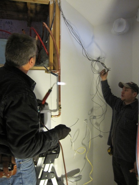
The plumbers installed the plumbing for the hydronic heating system. They had to assemble the components with soldered copper fittings, and to fit them into a relatively confined space. They did a professional job and the second photo below shows how it looked when they were finished. The paragraphs below describe the individual parts.
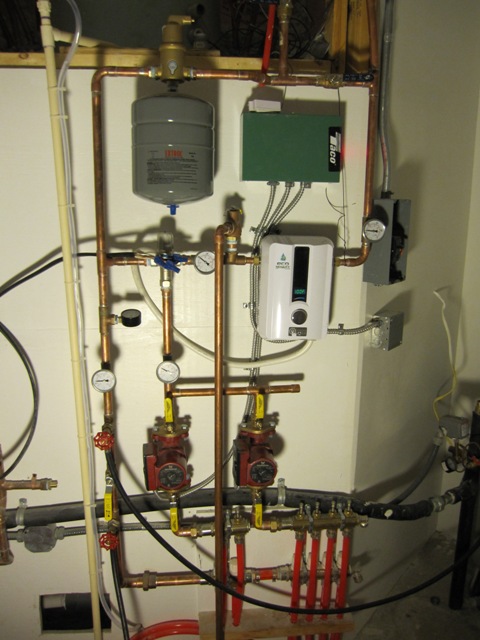
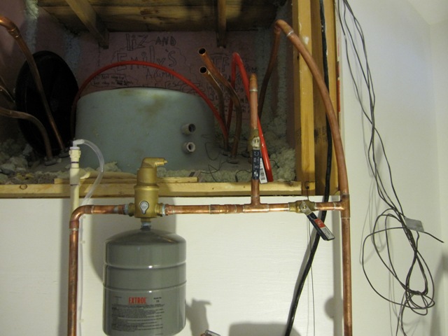
In the photo below, at the very top right are the pipes that feed water through one of the heat exchanger coils in the heat storage tank, the top of which is visible as the big light-blue thing in the back. The two blue-handled valves shown in this photo enable us to channel the water through this heat exchanger, or to bypass it entirely. The bypass mode is used when the tank is cold, as it is now, so that we can use the electric water heater to heat the house without having to also heat the storage tank. The big tank is still very cold because the solar heat collectors are not connected yet. Once the tank is warmed by the sun, we’ll start channeling the water through it in order to heat the house with stored solar energy. The brass device near the center of the photo is an air eliminator, which removes bubbles and dissolved air from the water. Below it is an expansion tank that keeps the pressure relatively constant as the water expands when it is heated.
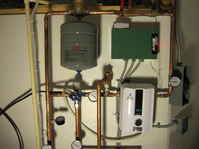
This photo shows, to the right of the gray expansion tank, the green relay box that enables each thermostat to control a pump. Below that is the EcoSmart hot water heater, which provides backup electric heat to the system when we don’t have enough heat from the solar collectors. At the moment it is set to deliver water at 100 degrees F, which gets mixed with a little of the colder water by the mixing valve to the left, and goes into the pumps at 90 degrees. We have it set this high because we’re trying to warm the house up quickly, and normally the heater will be set for about 80 degrees. As long as the solar-heated water coming out of the heat storage tank is warmer than that, the heater doesn’t switch on and we use free heat from the sun. But not today, alas, and the house isn’t up to temperature yet so we’re consuming over 6000 watts of electricity to warm up the house. That’s a lot but we need it in order to dry out the drywall compound on the walls.
The photo below shows the two pumps that circulate water through the system. The pump on the left circulates water through the radiant floor piping in the cottage, and the one on the right supplies the main house. Each one is controlled by an independent thermostat. The gauges on the left show the temperature of the warm water going to the pumps and the cooler water returning from the floors. In this photo, taken right after start-up with the floors still quite cold, the water is entering the floors at 90 degrees F and coming back at 60 degrees. That’s a huge temperature drop and not typical of what we expect once the floors are up to temperature.
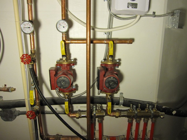
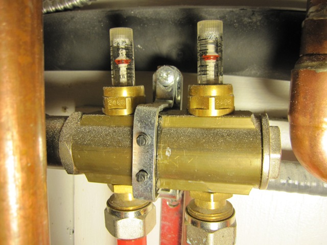
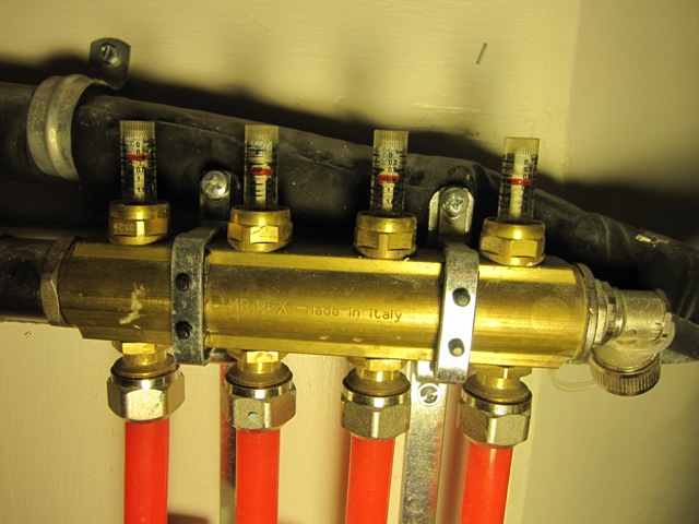
The manifolds at the bottom distribute the water from each pump out to the individual loops of tubing in the floors. The clear devices on the top are flow rate meters that show the water flow rate through each loop, and when turned they operate a valve for each loop so that the flow rates can be balanced.