September 5, 2009
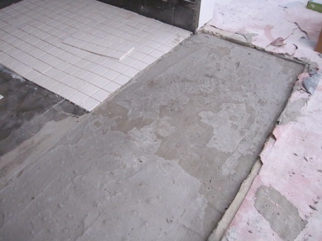
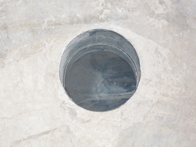
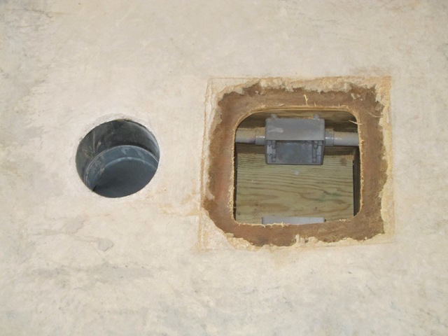
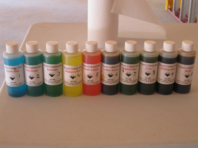
We purchased a sample kit of acid stains for concrete from Direct Colors. The kit includes 4-ounce bottles of the 10 stain colors that they offer. These stains are designed to react chemically with concrete to produce a variety of colors, mostly blues and browns. We cleaned a 30-inch wide area of the cottage floor that will eventually by covered by a cabinet, and applied each stain in a 3-inch-wide strip. Each strip is further divided in half, with the left half getting the stain full-strength and the right half getting the stain diluted 50% with water. The second photo below shows how it looked right after we applied the stain.
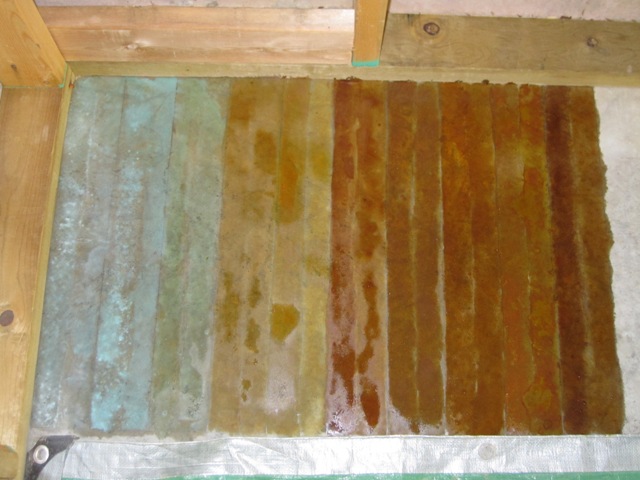
The first photo below shows the stain appearance after it had dried, and the second photo shows how it looks after thorough cleaning.
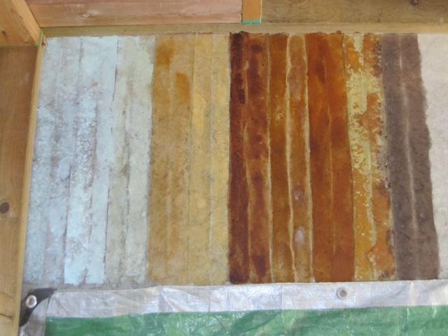
Some of the colors aren’t bad, but they aren’t exactly great either. And these stains pose some hazard in application due to the hydrochloric acid they contain, as well as for clean-up since some of them contain copper and chromium. A small area like this isn’t much of a hazard but spreading these nasty chemicals over thousands of square feet does not appeal to us! Fortunately we found an alternative called SoyCrete, a non-hazardous soy-based stain for concrete. We’ve ordered some samples, and we’ll do a similar test once they arrive.
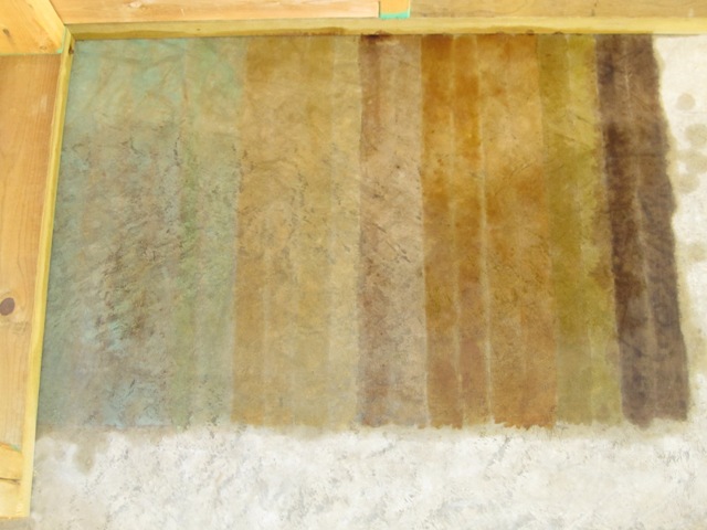
September 17, 2009
Liz applied the SoyCrete stain samples in an area near the first test. The colors in the photo below are not directly comparable to the acid stain photo above because the lighting is different, and the ones above were still a bit wet whereas these are dry. In general the colors are not bad, but not great either. We suspect that part of the problem is that the concrete was troweled a lot, which closes up the pores of the concrete and makes it less receptive to stain. We’re going to try etching the concrete with citric acid, i.e. lemon juice, which is a lot less toxic than the hydrochloric or phosphoric acid used in most concrete etch products. Then we’ll do some more stain tests to see if the etching makes a significant difference.


January 21, 2010
We finally settled on the SoyCrete stain, and chose the color ‘Augusta Green’ for all the floors in the house. Our nephew Nash did the hard work of scrubbing and washing all the floors with SimpleGreen general-purpose cleaner. Once they were clean, he applied Eco-Etch etching solution, which is a relatively nontoxic and nonhazardous etcher and cleaner also made by Ecoprocote and recommended for use with the SoyCrete stain. He applied one coat of etch using a paint applicator pad, and then a second coat after about 15 minutes. Then he washed it off with more SimpleGreen and rinsed it clean. This process leaves the concrete very clean with open pores that will absorb the stain better.

Initially we had Nash apply the stain using a sponge mop, which worked pretty well but it did leave some lap marks. Eventually he switched to sponging it on by hand, which gives a more even coverage.

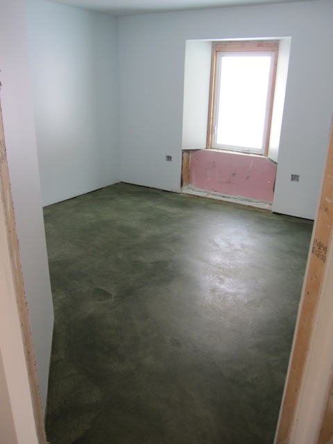
Here’s a photo showing one of the bedrooms shortly after the stain was applied. The stain is still a bit wet in this photo, but it will look similar to this once it has dried and has been sealed with sealer. The color will deepen somewhat after the sealer has been applied. The patterns in the floor come mostly from the varying surface texture and color of the concrete, and it looks rather like jade.
January 26, 2010
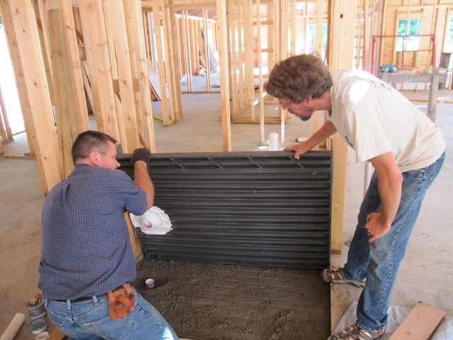
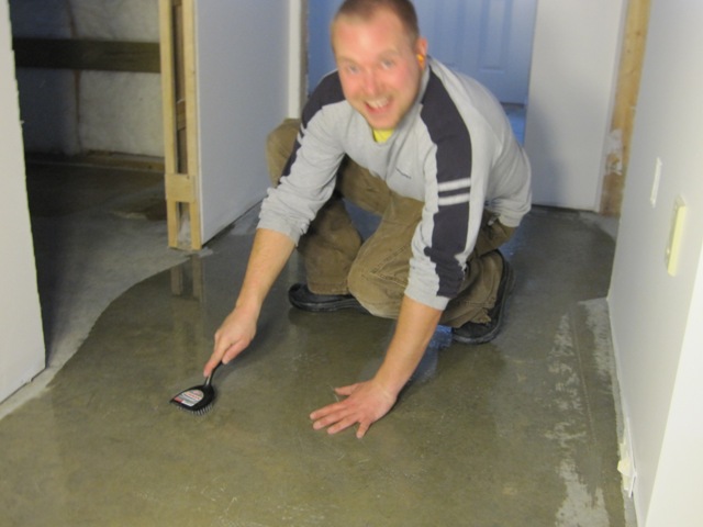
After cleaning and etching the floors in the main living space, Nash applied the floor stain. He used a new sponge applicator that spread the stain well, but it left a lot of streaks that didn’t look so good. After some experimentation we found that the best technique was to spread the stain, wait a few minutes for it to mostly dry, and then buff it with a damp sponge to even out the brush marks. It was hard work but it gave the best finish of any technique we’ve tried.
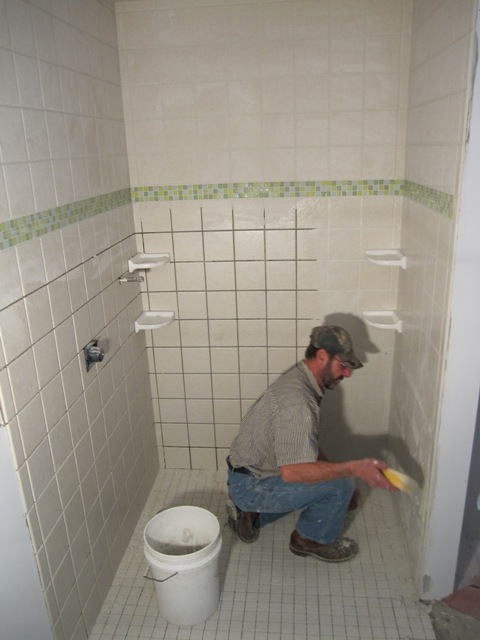
The first photo below shows Nash applying the stain as Liz buffs it out. The second photo shows the stained floor of the studio, with the living room beyond. The swirl patterns you can see in the second photo are not from unevenness in the stain application. They are due to surface irregularities made by the power trowel that was used to finish the concrete slabs.


We even found some shoe prints in the concrete, right in the living room! They were not visible until we applied the stain. This is just part of the character of stained concrete floors.

January 27, 2010
Liz and Nash sealed all the floors in the main house today. Liz sprayed on the AcriSoy sealer using a pump-up garden sprayer, and then Nash rolled it out with a paint roller. They applied just enough to wet the surface evenly so there was no puddling. The sealer absorbed into the concrete and was dry to the touch in about 15 minutes. After about an hour they applied a second coat.

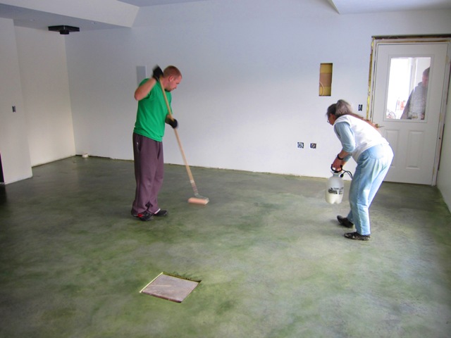
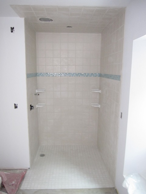
Here’s the final result. It’s a bit less green than we expected, since the hard-troweled areas did not absorb much stain and remained relatively gray, but we like the effect.

January 30, 2010
Liz and Bruce finished up the staining of the entryway floor. The first photo is looking south with the cottage great room behind, and the second shows the entryway looking west toward the front door. The light green rectangle on the left is a temporary spacer where the metal doormat will go.


January 31, 2010
Here’s the finished floor of the cottage looking north, with a little bit of the entryway floor beyond. Overall the floors look pretty uniform in color throughout the house, and the color variations in these photos are mainly due to different lighting at different times of the day.