Winter Wonderland Tour

Includes affiliate links that help offset our expenses at no cost to you. Affiliate programs and affiliations include Amazon Associates and the eBay Partner Network.

We took Our Adventure Van on a winter trip up to see Sleeping Bear Dunes and Tahquamenon Falls in February 2022. Temperatures were in the teens and below at night but the campgrounds at these parks have electric service so we used electric heaters to helped save on propane, and kept the van at about 60F at night.

At Sleeping Bear Dunes we hiked the Empire Bluff Trail, which gave some fantastic views of Lake Michigan about 400 feet below us:

Here’s a video from the lower Tahquamenon Falls, filmed with my DJI Pocket 2 gimbal and my Mavic Air 2S drone:

At the upper Tahquamenon Falls, I brought the Mavic Mini drone but the controller’s battery died due to the cold, so this video was filmed mainly with my Panasonic GH5 camera:

CNC Epoxy Inlay Backgammon and Cribbage Board

Includes affiliate links that help offset our expenses at no cost to you. Affiliate programs and affiliations include Amazon Associates and the eBay Partner Network.

I’m using my CNC router to make a travel-sized backgammon and cribbage board, inlaid with epoxy and colored mica powder.

Part 1 – Milling Stock, Cutting Pockets

In this first installment I introduce the project, mill the wood to size, and set up the CNC router to cut the inlay pockets on the backgammon board.

Part 2 – Backgammon Inlay

In the second installment I mix the mica and epoxy, and pour the inlays.

Part 3 – Special Details

In the third installment I add gold edges to the points on the backgammon board, and make the inlay and holes on the cribbage board side.

Part 4 – Finishing It Up

In the fourth and final installment I dye the wooden playing pieces and build the finished boxes with splined miter joints.

Resources

Here are links to some of the tools, materials and software that I’m using in this project:

AutoDesk Fusion 360 for personal use
Blender software
Next Wave CNC Shark Router
Carbide 2-flute Down-cut end-mills
Mica Powder for Epoxy Resin
West System Epoxy
Wooden checker pieces
Wooden cribbage pegs
Keda Aniline Dye 5 Color Kit

CNC Feeds & Speeds

UsageBitRPMDepth of
cut
Plunge
mm/min
Cut
mm/min
Comments
Roughing0.1250″ (3.18mm)
2-flute downcut
250003/32″ (2.38mm)500800
Finish0.0313″ (0.80mm)
2-flute downcut
250003/32″ (2.38mm)200250
Drill0.1250″ (3.18mm)
4-flute upcut
250000.25″ (6.35mm)
200n/aPeg holes
Engrave0.1250″ (3.18mm)
30-degree point
25000Variable400400V-carved text

Wood Dye Info

I dyed the playing pieces using a Keda Aniline Dye 5 Color Kit, and I mixed it following the manufacturer’s instructions but with a higher ratio of dye to water to get more concentrated colors. Here are the amounts of dye I mixed with 3 ounces of warm water:

Red: 1/8 teaspoon
Blue: 1/4 teaspoon
Green: 1/8 teaspoon yellow + 1/4 teaspoon blue
Purple: 1/8 teaspoon red + 1/4 teaspoon blue

Next time I use the blue dye, I’ll mix it with hot (not just warm) water in hopes of getting it to dissolve better.

Quick Mount Camera Boom

Includes affiliate links that help offset our expenses at no cost to you. Affiliate programs and affiliations include Amazon Associates and the eBay Partner Network.

I made a quick-release mount for this 7-foot camera boom to shoot videos from various locations in my workshop.

Here are links to the parts that I used:

Impact 7 ft HD Wall-Mounted Boom Arm
DMKFoto Heavy Duty Ball Head with Quick Release Plate
Konsait Black Camera 323 Quick Release Plate
IRWIN Step Drill Bit, 3/16-Inch to 7/8-Inch

The ball head listed above is inexpensive but its quick-release is not compatible with Manfrotto quick-release plates, which I use on all my gear. So I changed out the plate for the quick-release listed above. You can also get Manfrotto ball heads that come with their quick-release plate, and they’re a bit more expensive but good quality.

My main cameras are a Panasonic GH5 and a Panasonic G95, and prefer to use the G95 on the camera boom because it’s lighter weight. I also have an older Canon EOS Rebel SL1 that I used to shoot many of my previous videos and that’s what I’m showing on the camera boom in this video.

Cooking with Fire

Includes affiliate links that help offset our expenses at no cost to you. Affiliate programs and affiliations include Amazon Associates and the eBay Partner Network.

In this outdoor cook-off with the Fortune Bay Expedition Team, we challenged folks to cook something amazing using only a wood fire as the heat source. No fossil fuels, no alcohol stoves, no electric appliances. It was an opportunity to learn new outdoor cooking techniques while enjoying some amazing food and good company.

Also check out our video on building the Portable Wood Fired Pizza Oven.

Here are some links to the books that inspired this cook-off and that we gave away to the lucky winners, and some of the other cool gadgets we used:

How to Use a CNC Router for Shell Inlay

Here’s how I designed a shell inlay for a guitar headstock using Fusion 360, and cut the inlay using my CNC router.

Part 1 – Design in Fusion 360

Part 2 – Cutting Shell Material

Resources

Here are links to some of the tools, materials and software that I’m using in this project:

AutoDesk Fusion 360 for personal use
Next Wave CNC Shark Router
Carbide 2-flute Down-cut end-mills
1/32″ Carbide shell cutter
Phenolic backer board

CNC Feeds & Speeds

UsageBitRPMDepth of
cut
Plunge
mm/min
Cut
mm/min
Comments
Wood pocket0.0313″ (0.80mm)
2-flute downcut
250000.5mm roughing
0.2mm finish
200250
Shell0.0313″ (0.80mm)
shell cutter
250000.3mm125250

Fusion 360 Project File

Here is the Fusion 360 project file that I used for this design. It is set up specifically for my machine and cutting tools so I make no guarantees that it will work for you, but you are welcome to use it at your own risk.

DragonflyInlay.f3d

Fixing Insulation Problems

Using our new Thermal Imaging camera we were able to see some significant problems in the insulation of our exterior walls. The cellulose insulation was specified to be installed to a so-called “dense-pack” density, which compresses the material enough that it will not settle. But alas our contractor did not do it as specified, and in the 3 years since it was installed there has been significant settling in the walls. We had just a vague sense that the house was not retaining heat as well as it originally did, until we used a Thermal Imaging camera to make the problems visible.

Once we could see where the problems were, Jay had to crawl through the attic to the tops of the exterior walls and stuff more insulation down into them by hand. It was a very Dirty Job and not practical to photograph, but now that it’s done we can clearly see the difference in the infrared images. We can also tell the difference inside, where the bedrooms stay one or two degrees warmer than they did before with similar outside temperatures.

In the series of photos below, each set of three pictures shows a shot of an exterior wall area taken with a regular digital camera, followed by thermal images taken before and after fixing the insulation. The pictures are not framed exactly the same in each set since they were taken at different times, but in each case they show the same general area. The indicated absolute temperatures of the surfaces are not significant because we didn’t calibrate the camera for absolute temperatures, and the colors are not very significant either; what matters is the huge reduction in the temperature variation before and after. It’s plain to see where the walls had no insulation at all, and that filling them up made a big difference.

Visible Image

Thermal Image – Before

Thermal Image – After

In the very last photo above, you can see some cooler areas shown in blue along the corners of the walls. It is normal for surfaces to be slightly cooler in the corners because there is less interior air circulation there, but the significantly colder spot at the lower right of the photo cannot be explained simply by reduced air circulation. It is most likely a small gap remaining in the insulation, or perhaps a thermal bridge where the inner wall framing is tied to the exterior walls in a few places. It’s not a major concern because, although it is a couple of degrees cooler there, the area is so small that its heat loss is not significant.

Since the original insulation had 3 years to settle and the newly added insulation is packed in pretty tightly, there is a good chance that no further settling will occur. But since we decided to invest in the thermal camera we can re-check it every year to make sure no new problems arise. So far we’ve only done the walls in the main house, and the exterior walls in the cottage section also show some significant insulation settling that we’ll need to fix before next winter:


LEED Measures

Here is a list of some of the features of our home that qualify for LEED credits. This is not an exhaustive list, just some of the more interesting features:

  • Universal Design – every room in the home is usable by persons with limited mobility
  • Limit conventional turf – we will have no conventional turf at all, just gardens surrounding the house
  • Reduce irrigation demand – all our permanent plantings will have far less water demand than typical landscaping in this region
  • Water reuse – our rainwater harvesting system collects water from more than 50% of our roof, to be used for watering the gardens and flushing toilets
  • Indoor water use – all our toilets, lavatories and showers have very high efficiency fixtures that use much less water than conventional fixtures
  • Optimize energy performance – our home is designed to generate more energy than it consumes, using a combination of superinsulation, energy efficient appliances, active and passive solar heat collection, and solar electric generation
  • Construction waste reduction – our construction will generate about 1/10th as much waste per square foot as a typical home construction
  • Combustion venting – our wood stoves are EPA certified for low emissions, and have an outside combustion air supply to avoid drawing warm air from the house
  • Outdoor air ventilation – we use a heat recovery ventilator (HRV) to provide continuous ventilation, and to recover about 70% of the heat from the outgoing stale air
  • Local exhaust – our bathrooms are equipped with humidity sensors, which will increase the airflow through the HRV whenever excess humidity is present
  • Air filtering – the ventilation air intake is equipped with a high efficiency air filter (rated MERV 13) to reduce particulates in the incoming fresh air
  • Indoor contaminant control – we have a shoe removal and storage space near the front door, and a central vacuum system that exhausts to the outside

In addition, here are some of the environmentally preferable products in our home that earn LEED credits:

  • Floor – polished concrete generates far less emissions and traps far less dirt than carpet
  • Walls & ceilings – our drywall was made less than 200 miles away from 96% recycled material
  • Paints – All walls and ceilings use low-VOC paint
  • Countertops – we’re making our own countertops using recycled glass
  • Insulation – our cellulose wall insulation is about 85% recycled paper

Map Ruler Generator

Includes affiliate links that help offset our expenses at no cost to you. Affiliate programs and affiliations include Amazon Associates and the eBay Partner Network.

Instructions

This tool will generate a PDF document containing a printable map ruler with user-selectable scales. It can include custom pace scales, which enable you to directly measure distances in your own paces on practically any map. We’ve had good results using a Brother P-Touch PC-Connectable Label Maker to print rulers onto 18mm Clear Label Tape, and you can also print on letter-size paper with a regular printer.

This should work in most browsers, but we recommend Google Chrome. If you are using FireFox and the ruler keeps opening in a separate application, there is an option to display the ruler directly in this page: in your browser’s Settings menu, under Applications look for Portable Document Format (PDF) and change the action to Open in FireFox.

With Chrome and most other browsers you can print a ruler directly from the preview window above (look for a printer icon) but if your browser doesn’t support that, you can click the Open PDF button to open the document in a new tab. When printing, look for a ‘Scale’ setting in your print dialog and make sure to set the scale to ‘Default’, ‘Actual Size’ or ‘100%’ (this can vary depending on which browser you are using). Don’t select ‘Fit to Page’ or similar, because it will mess up the scaling.

When using a label printer you will need to open the Printing Preferences dialog for your printer and set the Width to match the Print Format setting, and the Length to match the Ruler Length setting (see below). Here is an example, although your printer driver’s dialog may look different:

Print Format

The Print Format setting lets you specify a standard label tape width, or a letter-size page for printing on an ordinary printer. This deterimines the page size of the PDF document that is generated.

Upper and Lower Units

The units of each side can be specified, and if “Paces” are selected then a Pace Count can also be specified. For the Pace Count, enter the number of paces (two steps) it takes you to travel 100 meters. If you don’t know this number you can measure it by marking out a known length such as 50 or 100 meters and walking it while counting your paces. Repeat several times and average the result. You may want to print a scale with a larger pace count for rough terrain where it will take more paces to cover a given distance.

Ruler Length & Height

This is the physical size of the ruler that is printed. When printing labels it is recommended to set the Height equal to the full width of the label tape, although the printer may clip the index lines a little at the top and bottom edges. You can also reduce the height to make the ruler slightly narrower than the tape to avoid this clipping.

Map Scale

Enter the scale printed on the map, or measure the map scale if necessary. Some maps may show a scale such as 1:24,000 but may not actually be printed at exactly that scale, so it’s best to measure some features on the map to check the actual scale. To get the scale factor, just divide the real-world size of a known feature (such as the distance between two road intersections) by the physical distance measured on the map in the same units such as meters. The drop-down list at the left lets you enter common map scales easily, but you can also type an arbitrary scale into the box to the right.

Printer Scale

This lets you fine-tune the scaling to match a particular printer, because printers don’t always print things at exactly the specified size. Adjusting this is usually not necessary because measuring distances by counting paces is an approximate technique that’s affected by things such as terrain, so if a ruler is off by 1% it probably won’t matter. But if you want your ruler to be as accurate as possible then you need to experimentally determine your printer’s scale factor.

A simple way to do this is to set the map scale to 1:10,000 and the printer scale to 1.000, and print a ruler that shows a range up to 1.0km. Then measure the physical length of 1.0km on the printed scale, which ideally should be 100mm. If it is not, divide the printed length by 100mm and enter this number into the Printer Scale box. For example if it prints 98.3mm wide then enter 0.983. Try printing again and the resulting print should be extremely close. You can tweak this value experimentally, keeping in mind that making the Printer Scale larger will make the printed ruler shorter.

Mirror Image

Checking this box produces a mirror image of the ruler. This can be useful to eliminate parallax by attaching a clear label to the underside of a plastic sheet as described below.

Printing Problems?

If printing directly from your browser doesn’t work right, it may work better to save the PDF document to your computer and then open it in Adobe Acrobat Reader in order to print it. You can use the ‘Download’ button in the PDF preview panel above if your browser provides one, or click the Open PDF button to open it in a new tab and then use your browser’s Save-As menu (Ctrl-S in Chrome) to save the file. Here’s an example (thanks to Bill who figured it out!) of the Brother PT-D600 properties and Adobe print dialog:

Practical Guidelines

Single-scale rulers can be printed as narrow as 6mm (1/4″), which works well for adhering directly to a compass like this:

Two-scale rulers work better when printed on 12mm (1/2″) or 18mm (3/4″) clear label tape and affixed to a sheet of clear plastic:

As shown in these images, you can measure paces quite accurately from orienteering maps if you align the index marks with the edges of the circles instead of the center.

The following are a few different methods to print and assemble this kind of ruler. For any of these methods, an ordinary paper punch works well to punch a hole on the right hand side (opposite the map scale) so you can keep your rulers together on a lanyard.

Easy

Use a Brother P-Touch PC-Connectable Label Maker to print a ruler onto 18mm (3/4″) Clear Label Tape, and stick the label onto a sheet of rigid clear plastic. The Mirror Image option is recommended so you can place the label on the underside of the plastic sheet, especially if the plastic is somewhat thick, because it puts the printing right on the map to reduce parallax.

A good source of clear plastic material for rulers is the clamshell packaging in which many products are frustratingly packaged, as it often has flat areas large enough to cut out ruler material. Another good source is the thin clear lids that come on things like boxes of chocolate. If you can’t find any recyclable material that’s suitable, office supply stores carry all sorts of items made of clear plastic that can be cut up and used.

Cheaper

If you don’t have a label printer, you can print a ruler onto plain paper or transparency film and then laminate it using a thermal laminator.

Cheapest

Print the ruler onto ordinary paper or heavy card stock, optionally apply clear packing tape on both sides to make it more durable, and cut it out. You won’t be able to see through it but it still works if you cut right up to the tick marks.

The Tank Springs a Leak

Includes affiliate links that help offset our expenses at no cost to you. Affiliate programs and affiliations include Amazon Associates and the eBay Partner Network.

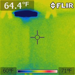
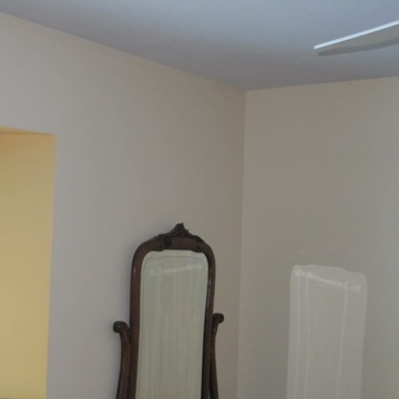
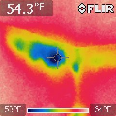
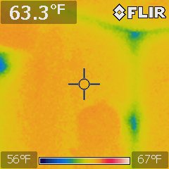
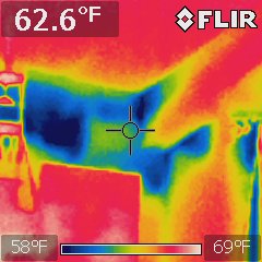
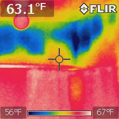
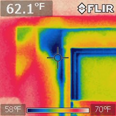
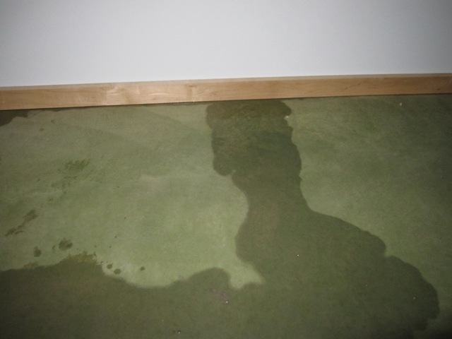
The disturbing sight of water seeping out from under these baseboards could mean only one thing: a leak from the 2500-gallon heat storage tank that’s on the other side of the wall. The water level gauge indicated that it had dropped about 10 inches meaning that we lost about 300 gallons before noticing the leak, and since there was only a trace of water on the floor the 300 gallons had to seep down into the ground under the concrete floor (which should be relatively harmless) and also up into the cellulose insulation that surrounds the tank (which is very bad).

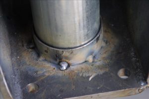
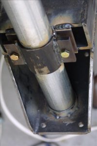
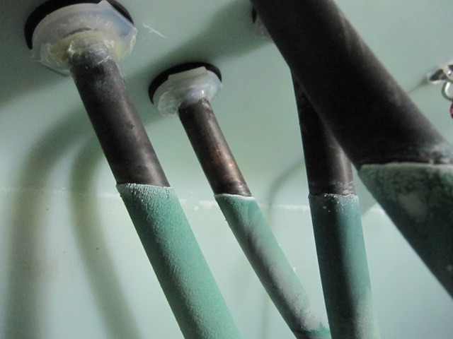
When constructing the tank we anticipated that it might develop a leak around the plumbing fitting at the bottom, which provides a way to drain the tank, so we left this fitting accessible through a hole in the wall of the mechanical room. As you can see below there is water underneath the fittings, but the underside of the fittings seems dry which suggests that the tank may have cracked somewhere else. We connected a hose to the drain line in order to carry the water out beyond the driveway, and then opened the big valve to drain the tank. That doesn’t fix the problem of course, but at least it keeps any more water from entering the house so we have time to devise a solution.

September 3, 2011
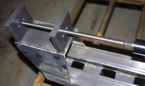
If the polyethylene tank is indeed cracked, it should be possible to repair it with a plastic welder. But first we have to solve the more difficult problem of removing the soggy insulation around the bottom of the tank. It’s possible to climb inside the tank through the top hatch which is accessible from the mechanical room, but the cellulose insulation around the bottom of the tank is thoroughly soaked and needs to be removed. In addition, we may not be able to locate the leak without removing all the insulation. The 8-foot diameter by 7-foot high tank is surrounded on all sides by 12-16″ of cellulose insulation packed between the tank and the walls that contain it, and there’s about 4 feet of insulation on top of it which means we need to move a total of over 20 cubic yards of insulation! For comparison, that’s about the capacity of this Peterbilt 357 dump truck:

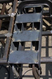
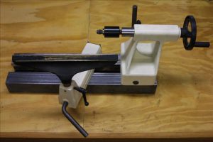
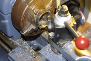
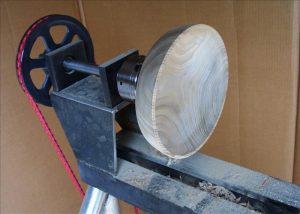
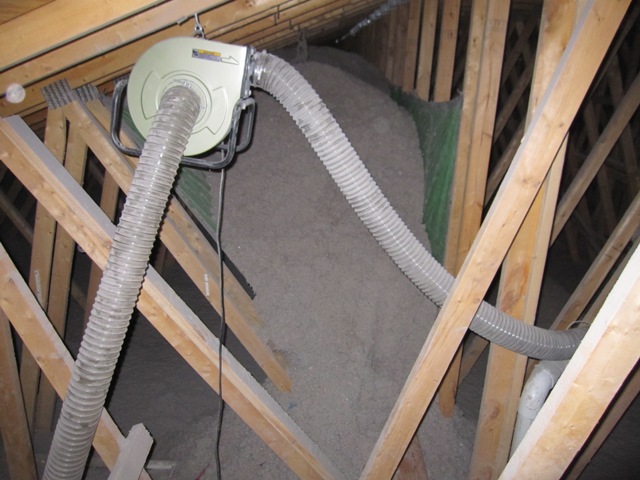
Moving all this material is going to be a big, messy job! After pondering the problem for a while, we’ve come up with a way that we think will enable us to move all the insulation from around the tank into the attic above the garage, and then to move it back around the tank when the repair is done. What we want is a “vacuum” with a hose that will suck up the insulation from around the tank and blow it out through another hose. Shop-vac type vacuums won’t work because they will only collect material into a sealed cannister and even a large 20-gallon shop vac would have to be emptied 200 times to move this much material. And a typical cellulose insulation blower won’t work because it’s designed to have insulation bales dumped into it from the top and doesn’t provide a vacuum-type suction hose. What we’re going to try is a small single-stage dust collector that we bought from Harbor Freight:

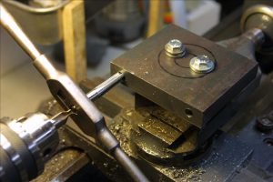
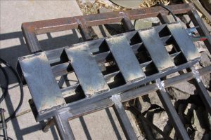
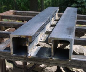
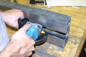
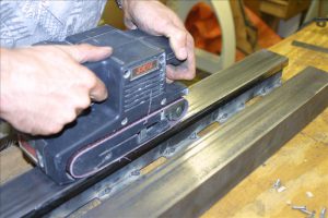
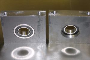
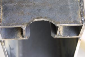
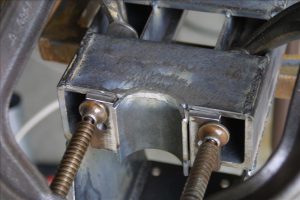
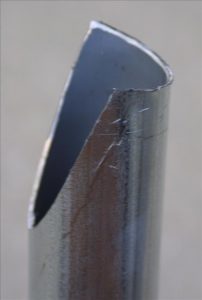
This unit is designed to suck in wood chips and sawdust and to blow them into a large filter bag. By connecting an outlet hose instead of the filter bag, it should be able to suck up the insulation material from around and over the tank and blow it into the attic, and then to reverse the process after we fix the tank. The photos below show the protective screens within the inlet and outlet openings, and these will have to be removed because the cellulose would easily clog the inlet screen. This also creates a safety hazard so we’ll make sure the inlet and outlet hoses are very securely attached, and we’ll also keep a shut-off switch close by in case the unit sucks in anything that causes a jamb. Try this at your own risk!

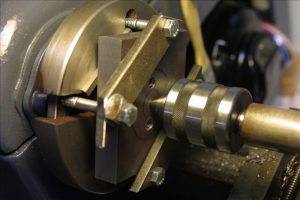
Removing the screens was easy, and revealed a pleasant surprise. We thought a low-end dust collector like this would have a plastic impeller but it is actually steel. The steel impeller should be able to take the abuse we’re about to give it. Tomorrow we will put it to the test.

September 4, 2011
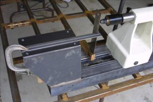
The first photo below shows the top of the tank area, covered in several feet of insulation. In order to store the 20+ cubic yards of material, I secured tarps into the bays of the roof trusses to create giant storage bins. The dust collector is hung from a truss so that it will blow insulation into the bin through a 10-foot outlet hose, after drawing it up through a 20-foot inlet hose.

Here’s how things looked after about an hour of blowing. The dust collector is working extremely well! The top of the tank is now visible after removing the first several feet of insulation, and the bin is filling up fast. The volume of insulation around the tank is about 20 cubic yards but it’s packed densely so it is expanding quite a bit in volume as passes through the blower, and will be more like 30 cubic yards once it’s all removed.

September 5, 2011
The blower continues to perform very well and has removed almost all of the insulation. There was no noticeable dampness until the last 6 inches or so on the bottom. At that point I redirected the blower’s outlet hose to blow the slightly-damp insulation out into the attic, where it will dry out and will just add a little insulation over the living room. That way we’ll only be putting dry material back around the tank after repairs are done.

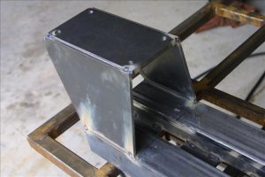
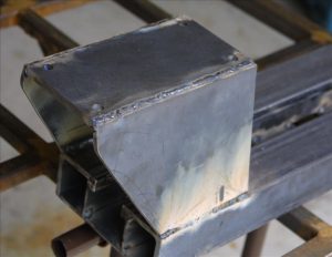
It took a total of about 4 hours with the blower to remove all the insulation, plus a couple of hours to set up the equipment and tarps. Here are photos showing the two truss bays filled with about 30 yards of insulation that was removed. Once repairs are complete we’ll blow all this back around the tank.

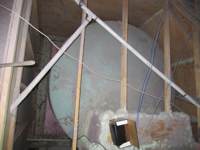
The last 2 inches or so on the bottom was pretty wet and the blower wouldn’t lift it, so I scooped it into trash bags and hauled them up on a rope. In all it’s only a small about of material that we’ll have to discard. Here’s how the tank looks now that it’s fully exposed. There is no apparent damage from the water and it’s all exposed to dry out.

September 10, 2011
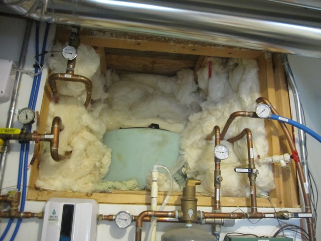
The next task was to remove the fiberglass insulation packed around the tank hatch and plumbing. We used fiberglass in this area instead of cellulose in order to make it easier to access this area if needed. Next I’ll cut an opening in the plywood above the hatch so it can be accessed from the attic above.

September 12, 2011
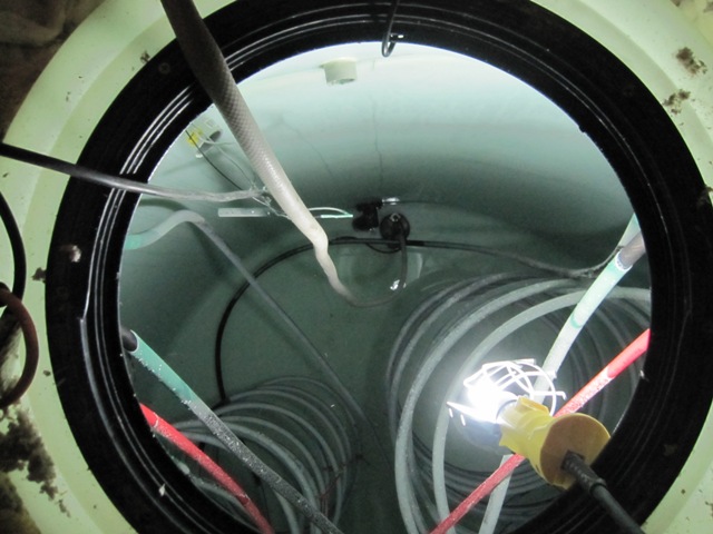
Once the hatch was open, I used a small submersible pump to remove the remaining few inches of water. These views are looking down into the tank from the attic.

September 17, 2011
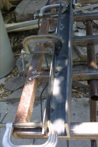
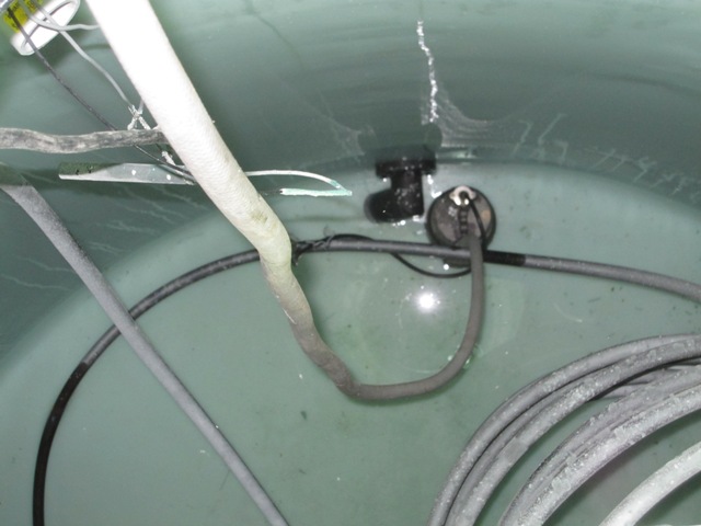
Here are some images taken down inside the tank. The copper heat exchanger pipes are covered with dark cupric oxide, which is formed when the copper reacts with oxygen in the water and it actually protects the copper from further corrosion. There are also some white mineral deposits from calcium in the water.

The mineral deposits were especially noticeable near the top of the water level, where they have grown fairly thick and are tinged with blue from copper dissolved in the water. The water tends to be the hottest at the top of the tank, causing the formation of more calcium scale.

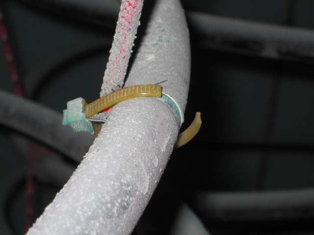
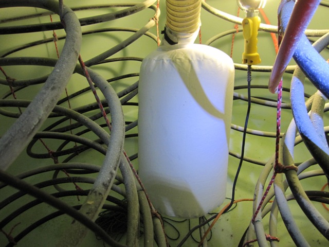
Some problems were immediately evident. After 2 seasons of use, the nylon cable ties used to secure the tubing to the support ropes had become brittle, and about half of them had broken. These were put in place during the tank construction in order to prevent the pipes from rubbing against the ropes causing abrasion of the copper. The pipes are supported using knots every 3rd coil or so, and the knots are still in good shape. The polypropylene rope shows no signs of degradation.

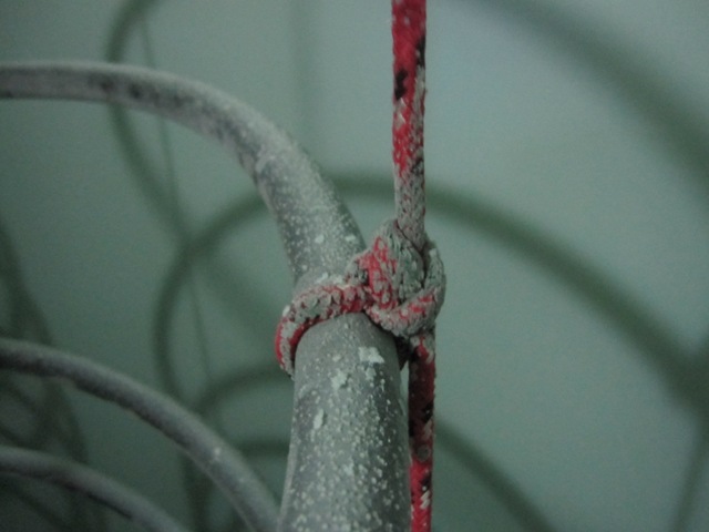
The first photo below shows where one of the coils has shifted, placing it in direct contact with one of the vertical copper tubes leading to the bottom of a coil. Over time this could lead to failure of the tubing at this point, due to abrasion where the tubes touch each other and rub together when the coils move slightly due to changes in fluid flowing through them. This will be easy to fix, by bending the vertical tube out of the way. The second photo below shows one of the PEX tubes that holds a temperature sensor. Originally it was held away from the copper by a nylon cable tie, which has broken allowing the PEX to rub against the copper. This could also lead to failure over time and it will be simple to fix it now.
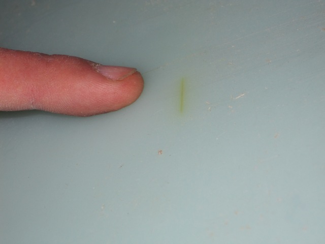
THE CRACK
Here at last is what caused all the trouble, or at least we hope this is the only cause! The crack is only about an inch long, and is on the side wall about 8 inches up from the bottom of the tank. It was difficult to photograph well but it’s definitely a crack that extends all the way through the wall. The first photo shows it illuminated from inside the tank and the second photo, also taken inside the tank, is with light shining through from the outside. There is evidence of an impact at this location, as if something hit the wall during manufacturing or transport and caused it to crack, and it is brown-colored as if water has seeped through and left some deposits behind. Apparently it has been there since we installed the tank, gradually increasing in size until it had finally cracked all the way through the wall and let water seep through. Overall the tank does not seem to have gotten brittle from the sustained high temperature (140 degrees F), so this appears to be an isolated problem.

THE REPAIR
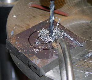
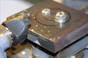
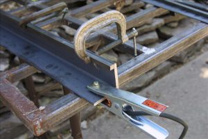
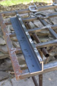
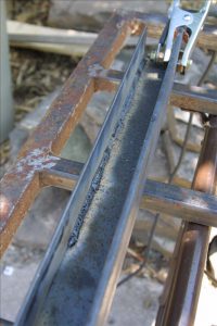
Repairing the crack was very simple, compared to all the work of draining the tank and removing the insulation around it. FIrst I drilled small holes at each end of the crack to keep it from propagating any further. Then I ground out a V-shaped channel about halfway through the tank wall, on both the inside and the outside of the tank.

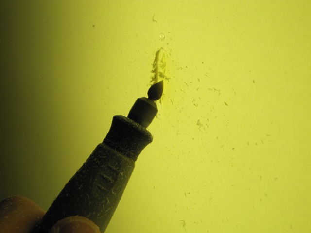
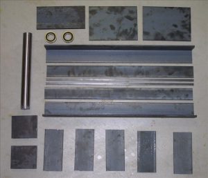
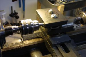
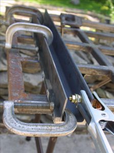
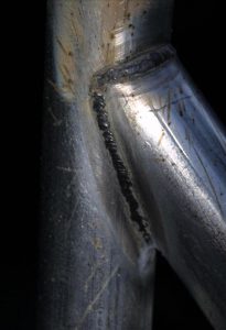
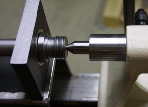
To repair the tank wall I used a Urethane Supply Co. Mini-Weld Model 6 Airless Plastic Welder, Model# 5600HT. It is like a large soldering iron but has a special tip through which a 1/8″ plastic rod is inserted. It comes with a variety of different kinds of plastic rods, and has a temperature control for welding various kinds of plastic including polyethylene which is the material of this tank. The welder melts the plastic rod together with the tank wall, filling the V channel and fusing it all together. It makes a bit of smoke and fumes as it melts the plastic so I used the outlet hose of the insulation blower, together with the filter bag that came with it, to provide a very effective fresh air supply inside the tank. I also wore a respirator with activated carbon filter cartridges so I wouldn’t be breathing any plastic fumes. It wasn’t practical to photograph the welder actually making the weld because it takes two hands (one to hold it and one to feed in the plastic rod), but the second photo shows it starting to heat and soften the tank wall around the V-channel. As soon as it was softened a bit I fed in the plastic rod and started filling in the V-channel I had ground out, and then went back over it all to melt the new plastic together with the tank wall.

I welded the crack both inside the tank and outside. The resulting weld looks ugly because it contains little bits of dark burned plastic that were left on the welder tip from when I tested it earlier. But it is nice and solid, having filled in the V-channel nicely and having fused it all together. It appears very unlikely to leak or crack again in this location.

October 4, 2011
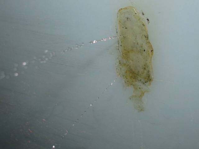
After refilling the repaired tank with 55-degree water from the well, we began warming it up with the solar heat collection system It took about 2 weeks to reach 100 degrees F, and then it leaked again! Fortunately we hadn’t replaced any of the insulation yet, since we were waiting to make sure the repair would hold. Obviously it didn’t, and the photos below show that it’s leaking right through the middle of the crack in two places.

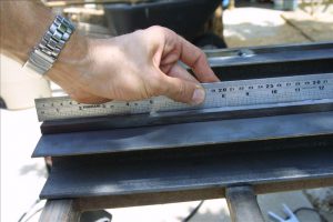
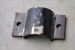
It’s not entirely clear why the repair failed, but a likely cause is that the plastic welding rod that came with the repair kit is made of low-density polyethylene whereas the tank is high-density polyethylene. The difference in chemical composition of the plastics may have prevented them from making a good bond, or it may have made them expand at different rates as the tank warmed up. It’s also possible that the V grooves I carved into the tank just weren’t deep enough, causing stress around the old crack to propagate into the repair material. In order to make a new repair with the same material as the tank, I harvested some plastic from the raised numbers molded onto the side of the tank to indicate the fluid volume. We can’t see them anyway once the tank is insulated, and this should make a better repair.

After grinding out the faulty repair, and creating deeper V grooves on the inside and outside, I melted these numbers back into the crack. I also applied heat to the area longer, to make sure that the repair material was fully melted into and blended with the tank wall. Sorry, no photos of that but visually it looks about the same as it did before.

October 15, 2011
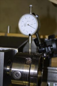
Before refilling the tank, I installed a leak detector to give us an early warning in case it ever leaks again.I ran some speaker wire around the outside of the tank and scraped the insulation off at several points, placing it under the edge of the foam insulation that the tank sits on. I ran the wire out into the utility room, where I connected it to a Reliance Controls THP205 Sump Pump Alarm and Flood Alert. The alarm is quite loud and it should sound the moment any water reaches the wire.

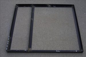
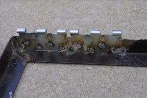
Before replacing the cellulose insulation around the tank, I placed a 6-inch layer of foam packing peanuts around the perimeter of the tank and covered it with some landscape fabric. That way the cellulose should remain at least 6 inches above the bottom of the tank so if we do have a leak this should keep the bulk of the cellulose insulation away from the water. If the foam peanuts ever get wet they won’t degrade and they have enough air spaces to dry out eventually. I also boxed in the area around the repair with some scraps of foam board and filled the box with foam peanuts so that if it leaks in the same area again, I can get to it by cutting a small opening in the adjacent wall. Hopefully it will never leak again but just in case, this should make it possible to repair without removing all that cellulose again!

January 6, 2012
After refilling the tank again and waiting a few weeks with no leakage, I replaced all the cellulose insulation using the insulation blower. It wasn’t practical to take photos during the process but it was pretty much the reverse of removing the material. It went reasonably fast and took about 4 hours. It has now been about 10 weeks since we refilled the tank. The water alarm has remained silent and the repair has held, and we are once again heating the house with stored solar heat.

Portable Bowl Lathe Construction

Raw Materials

I ordered most of the steel I needed from Metal Express and they have a branch nearby so I avoided shipping charges. I ordered the 2” ball bearings and the1.5” drill rod that I used for the lathe spindle from Enco. Here’s a picture of the steel plates and angles, plus the bearings and the drill rod for the spindle.

Preparing the Pillow Blocks

Because the steel was rough-cut I needed to flatten the bottoms of the pillow blocks, and then drill and tap them for 3/16” bolts. I drilled a couple of holes in them in order to mount them to the top slide of the metal lathe. This was an easy and solid way to mount them, although it made it harder to bore the bearing holes later. I squared them as best I could to the headstock to minimize how much I’d have to cut.

I used a fly cutter to flatten the bottom face of each block so it would sit solidly and squarely on the headstock.

I drilled and tapped holes in the bottoms for 3/16 bolts to hold them to the headstock.


I drilled 4 bolt holes in the top plate of the headstock in order to attach the pillow blocks. I drilled them a bit oversize (7/16”) so I’d have some room to slide the pillow blocks around in order to align them.

Welding the Bed

I started welding the bed by attaching the 3/8” square clamping strips to the 2” angle. These strips make the top of the bed the same thickness (5/8”) as the bed on my Jet lathe so that I can interchange the tool rest and tailstock between the two lathes without having to adjust the clamps. They don’t have to take any force and the inner surface will have to be ground smooth so I just tack welded them in several places. In the photos below, the angle is on its side so that what will become the top surface of the bed is to the right.


Then I welded on the 1/8” support strip that goes between the top of the bed and the cross plates on the bottom. In the photos below the piece is upside-down so the top surface of the bed is on the bottom. First I tack welded it on the inside just to hold it in place, then I went back and welded a continuous seam all the way down (the third photo shows it welded partway).

The inner surface of the ways must be ground flat so that the tool rest and tailstock can slide along it. I ground it approximately flat at this stage, but more grinding will be needed later to get the spacing just right.

After both halves of the bed were welded up, I laid them out with spacer blocks in between to get the spacing right. I made the spacer blocks just a little short, so that the gap between the halves was just a little too narrow for the tailstock to slide in. This way I can grind it afterward for a good fit. Then the bottom support plates are laid on and welded.

You can see below that the support strip on the left twisted a little so it’s not quite vertical – a cosmetic flaw but it won’t affect anything. By design, the gap is a little too narrow for the tailstock to slide in. I got a good sliding fit by carefully grinding the inside surface, checking often for straightness and the right gap. Then I sanded down the top surface of the ways, just enough to make them smooth (but not perfectly so). The tool rest and the tailstock fit reasonably well. I ended up with just a little side-to-side playin the tailstock, from grinding the insides of the ways a little more than necessary, but it won’t have much effect on the operation of the lathe.

Welding the Headstock

In order to position the top plate of the headstock correctly I made a wooden spacer box. With the top plate resting on this box I aligned the top plate using the tailstock so that it was accurately centered and lined up along the axis of the lathe. This is not a critical alignment because the bearing holes in the pillow blocks aren’t bored yet. I laid up the angled sides of the headstock and tack welded them together, then I removed the box and welded everything solidly. My welds aren’t very pretty, but at least they’re strong. I ground down the welds on the top plate so that the pillow blocks will sit solidly on the plate surface.

Marking the Pillow Blocks

I bolted the front pillow block to the top plate, positioning the bolts about in the middle of the oversize holes in the plate so I’ll have a little wiggle room in all directions. Using the tailstock I marked the center of the block and then precisely bored a ½” hole in it. I made an “arrow” out of ½” drill rod and turned it to a point at one end. This goes from the center in the tailstock, through the hole in the front pillow block to the rear pillow block. I marked where the point touched as the center of the rear bearing.

Boring the Pillow Blocks

I bored out the 2” holes for the bearings, leaving a narrow shoulder against which each bearing will seat. It took a long time to bore them out, and the mounting holes I drilled earlier made it a bit rough until I had bored past them. I tried to get a close fit but loose enough for the bearings to slide just a tiny bit to help alleviate any axial misalignment of the blocks when mounted to the headstock so the spindle wouldn’t bind. The fourth picture below shows the blocks upside-down (with the bolt holes on the top); the one on the left shows the front side where the bearing slides in and the one on the right shows the back side where the bearing seats against the shoulder. I made sure the shoulder was narrow enough that I could drive a bearing out by tapping on the outer race.

Making the Clamp

The headstock clamps on to a vertical support post, with the top of the post fitting into a tapered receiver under the top plate. I made the clamp from 2” black steel plumbing pipe, and the inside diameter is a bit too small to fit around the 2” conduit of the support post so I flattened it slightly before cutting it apart. The outer part of the clamp has two wings welded to it, with slightly oversized (7/16”) holes for the 3/8” bolts. I bored the receiver with a 3-degree taper so that it fit snugly around the conduit at its narrow (top) side.


Welding the Clamp

The plate on the bottom of the bed is notched to fit the clamp. I leveled the bed and then used a level to align the clamp and the receiver before welding them on. I just tack welded the receiver in several places to avoid distorting it too much. Beside the clamp on the back of the bed I welded two wings with 3/8” tapped holes for the bolts. In these photos the headstock is upside-down.

Making the Base Frame

I welded up a frame for the base from some 1/8” thick, 1.5”wide steel angle I recycled from an old bed frame. This later turned out to be too flimsy so I ended up welding on ¼” plates to the outside. It would have worked better if I’d started with ¼” thick angle instead. The center brace of the frame will extend right beneath the posts that support the headstock and tail of the lathe. Onto the frame I welded 3/8” coupling nuts, which were 1.75”long cut in half to make nuts about ¾” long. These are welded at 5 points on the frame to make the attachments for the legs. I used loose-pin hinges for the motor mount, drilled out (very slightly) to accept a ¼” rod through both hinges. The hinges are welded onto the base frame where the motor will attach, with the hinge rod through both of them while welding to keep them aligned.

Making the Legs

I made the legs from 2” thin-wall electrical conduit because it’s cheap (about $1/foot at Home Depot), reasonably lightweight, and quite stiff. In order to join the tubes I had to cope them, and I determined the profile using a wye joint calculator that I originally created for making Y branches in my dust collection ducts. I set the duct diameters to 2.2” and entered the angles I needed, and printed out the branch duct profile that I marked on the end of the tube. Then I just cut the profile with a saber saw. I got a pretty good fit, but I had to bend the “wings” out a little to account for the inner diameter of the branch tube mating to the outer diameter of the main tube. I welded the tubes to 3/8”thick by 2” wide steel plates at the bottom, through which I drilled the bolt holes for attaching to the base (I cut and drilled these plates and made sure they bolted to the base before cutting the tubes). While welding these tubes I made sure to avoid breathing any zinc fumes from the galvanized coating.

Making the Spindle

I made the spindle from a 12.5” long piece of 1.5” W-2 drill rod. I chose W-2 steel simply because I happened to have some, but I didn’t heat treat it in any way. First I squared off each end and drilled center holes so I could mount it between centers.


I cut a shoulder to mark the end of the main shaft, where the flange will seat against the front bearing. I turned the main shaft down to a little under 1” diameter in between the bearing areas, and then turned it to exactly 1” at the bearing points, using the bearings to check the fit often. I used some 320-grit wet/dry sandpaper to finish the surface for a nice snug fit in the bearings. I turned the end of the spindle down to ¾” to fit the sheave for the drive belt.

The spindle nose is threaded to match my Jet lathe so that I can use the same faceplate and chuck. Beyond the threads is a “locking groove” for the set screws of the faceplate or chuck, and I just turned this to match the dimensions of the Jet spindle. I cut the threads by angling the top slide to 30 degrees (half the 60-degree thread angle) and advancing the cut using the top slide rather than straight in using the cross slide. This is a technique I learned from The Amateur’s Lathe that puts a lot less stress on the lathe than feeding the threading tool straight in.

This completes the spindle. I did not bore it out for a Morse taper because I don’t need a drive center for bowl making. If I ever need a drive center I’ll make one that threads onto the spindle, which should be considerably simpler than drilling through the spindle and cutting an accurate inside Morse taper. Having a solid spindle also precludes using a vacuum chuck but if I ever want to use one I could still drill a small hole through the spindle.

Truing the Motor Pulley

I bought a fairly cheap step pulley for the motor shaft and it was not very well made, with molding flash in the grooves and a poor finish. I put it on the lathe and trued it up by setting the top slide angle to match the groove angle (17 degrees) and taking a light cut across each face.

Aligning the Bearings

With the spindle mounted on the headstock I aligned the front bearing by centering the spindle on the tailstock center. To align the rear bearing I mounted a wooden dowel in the chuck and rotated it to determine the center of rotation out on the dowel end (which need not be in the center of the dowel). If everything is aligned correctly the center of rotation will meet the tailstock center, and I shifted the rear bearing side-to-side to align it horizontally. I expected that I would have to shim one or both pillow blocks to get things aligned vertically, but it came out extremely close without any shims. I found that the spindle rotation got a little tight when I tightened down the bolts, because the bottoms of the pillow blocks were not fly-cut exactly square to the faces. I expected this and figured I’d have to shim them a little to get them square. One thickness of aluminum foil under the rear edge of the front pillow block did the trick. I checked the spindle run out with a dial indicator on the edge of the chuck and it was only 0.001” worse than my Jet lathe. Not too bad for a first try, and plenty good enough for making wooden bowls!

Mounting the Motor

I bought a 1-HP motor at Fleet Farm, and spent a bit extra for a ball-bearing motor so that the belt tension won’t prematurely wear out the bearings. I mounted the it to a 11”x14” piece of plywood and attached the hinges at the back. I wired in a power switch and a reversing switch so I can reverse the motor while sanding. I found a decent and reasonably cheap 20-amp power switch at Woodcraft, and removed the outlet so I had a place to mount the reversing switch. I welded some tabs on the rear lathe support leg so I can just hook the switch box to the leg and remove it easily for transport.

Making Bowls!

I set up for a first test in the garage, and turned a 10”bowl out of catalpa. It’s a fairly low-density wood so this was not a severe test of vibration, but I found that the lathe vibrated quite a bit until I got the blank trued up. After that it wasn’t too bad and I was able to turn a decent bowl. I moved the lathe out into the yard to see whether it would be less vibration-prone when sitting on grass instead of concrete (where the uneven surface means the base doesn’t make contact all the way across). It was a bit better on grass and I turned a larger 12” bowl, which came out pretty good. There was still quite noticeable vibration when the blank was rough and not balanced, and it seemed that part of the problem was that the base was too flexible so I welded ¼” thick by 1.5” wide steel all around the outer edge and across the center brace of the base frame to stiffen it.

I also found that the belt slipped when rough-turning the blank at the low speed (with the smallest pulley). The weight of the motor just wasn’t enough to hold sufficient belt tension so I added a clamp to the support leg that will hold the motor board down and provide enough tension on the belt.

Painting

Once I was satisfied that I wasn’t going to be altering the base or the lathe body, I primed all bare metal on the base frame and the lathe body using a metal primer and then painted them with two coats of a rust-inhibiting spray enamel. First I removed the spindle and bearings and masked off the inner surfaces of the pillow blocks with high-quality masking tape. I also masked off the top surfaces of the lathe bed.