Includes affiliate links that help offset our expenses at no cost to you. Affiliate programs and affiliations include Amazon Associates and the eBay Partner Network.
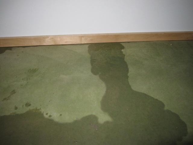
The disturbing sight of water seeping out from under these baseboards could mean only one thing: a leak from the 2500-gallon heat storage tank that’s on the other side of the wall. The water level gauge indicated that it had dropped about 10 inches meaning that we lost about 300 gallons before noticing the leak, and since there was only a trace of water on the floor the 300 gallons had to seep down into the ground under the concrete floor (which should be relatively harmless) and also up into the cellulose insulation that surrounds the tank (which is very bad).

When constructing the tank we anticipated that it might develop a leak around the plumbing fitting at the bottom, which provides a way to drain the tank, so we left this fitting accessible through a hole in the wall of the mechanical room. As you can see below there is water underneath the fittings, but the underside of the fittings seems dry which suggests that the tank may have cracked somewhere else. We connected a hose to the drain line in order to carry the water out beyond the driveway, and then opened the big valve to drain the tank. That doesn’t fix the problem of course, but at least it keeps any more water from entering the house so we have time to devise a solution.

September 3, 2011
If the polyethylene tank is indeed cracked, it should be possible to repair it with a plastic welder. But first we have to solve the more difficult problem of removing the soggy insulation around the bottom of the tank. It’s possible to climb inside the tank through the top hatch which is accessible from the mechanical room, but the cellulose insulation around the bottom of the tank is thoroughly soaked and needs to be removed. In addition, we may not be able to locate the leak without removing all the insulation. The 8-foot diameter by 7-foot high tank is surrounded on all sides by 12-16″ of cellulose insulation packed between the tank and the walls that contain it, and there’s about 4 feet of insulation on top of it which means we need to move a total of over 20 cubic yards of insulation! For comparison, that’s about the capacity of this Peterbilt 357 dump truck:

Moving all this material is going to be a big, messy job! After pondering the problem for a while, we’ve come up with a way that we think will enable us to move all the insulation from around the tank into the attic above the garage, and then to move it back around the tank when the repair is done. What we want is a “vacuum” with a hose that will suck up the insulation from around the tank and blow it out through another hose. Shop-vac type vacuums won’t work because they will only collect material into a sealed cannister and even a large 20-gallon shop vac would have to be emptied 200 times to move this much material. And a typical cellulose insulation blower won’t work because it’s designed to have insulation bales dumped into it from the top and doesn’t provide a vacuum-type suction hose. What we’re going to try is a small single-stage dust collector that we bought from Harbor Freight:

This unit is designed to suck in wood chips and sawdust and to blow them into a large filter bag. By connecting an outlet hose instead of the filter bag, it should be able to suck up the insulation material from around and over the tank and blow it into the attic, and then to reverse the process after we fix the tank. The photos below show the protective screens within the inlet and outlet openings, and these will have to be removed because the cellulose would easily clog the inlet screen. This also creates a safety hazard so we’ll make sure the inlet and outlet hoses are very securely attached, and we’ll also keep a shut-off switch close by in case the unit sucks in anything that causes a jamb. Try this at your own risk!


Removing the screens was easy, and revealed a pleasant surprise. We thought a low-end dust collector like this would have a plastic impeller but it is actually steel. The steel impeller should be able to take the abuse we’re about to give it. Tomorrow we will put it to the test.

September 4, 2011
The first photo below shows the top of the tank area, covered in several feet of insulation. In order to store the 20+ cubic yards of material, I secured tarps into the bays of the roof trusses to create giant storage bins. The dust collector is hung from a truss so that it will blow insulation into the bin through a 10-foot outlet hose, after drawing it up through a 20-foot inlet hose.


Here’s how things looked after about an hour of blowing. The dust collector is working extremely well! The top of the tank is now visible after removing the first several feet of insulation, and the bin is filling up fast. The volume of insulation around the tank is about 20 cubic yards but it’s packed densely so it is expanding quite a bit in volume as passes through the blower, and will be more like 30 cubic yards once it’s all removed.


September 5, 2011
The blower continues to perform very well and has removed almost all of the insulation. There was no noticeable dampness until the last 6 inches or so on the bottom. At that point I redirected the blower’s outlet hose to blow the slightly-damp insulation out into the attic, where it will dry out and will just add a little insulation over the living room. That way we’ll only be putting dry material back around the tank after repairs are done.

It took a total of about 4 hours with the blower to remove all the insulation, plus a couple of hours to set up the equipment and tarps. Here are photos showing the two truss bays filled with about 30 yards of insulation that was removed. Once repairs are complete we’ll blow all this back around the tank.

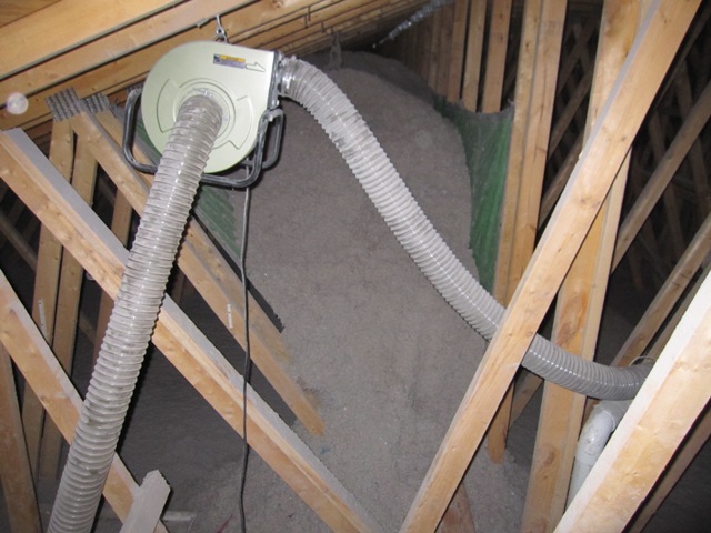
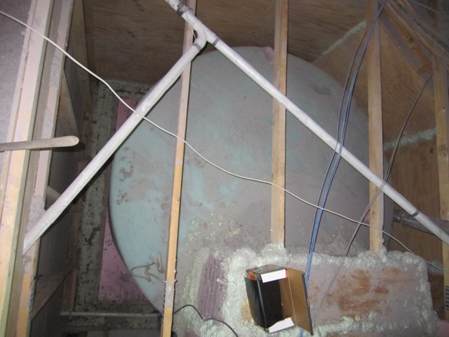
The last 2 inches or so on the bottom was pretty wet and the blower wouldn’t lift it, so I scooped it into trash bags and hauled them up on a rope. In all it’s only a small about of material that we’ll have to discard. Here’s how the tank looks now that it’s fully exposed. There is no apparent damage from the water and it’s all exposed to dry out.
September 10, 2011
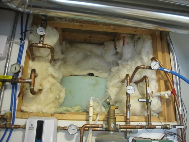
The next task was to remove the fiberglass insulation packed around the tank hatch and plumbing. We used fiberglass in this area instead of cellulose in order to make it easier to access this area if needed. Next I’ll cut an opening in the plywood above the hatch so it can be accessed from the attic above.

September 12, 2011
Once the hatch was open, I used a small submersible pump to remove the remaining few inches of water. These views are looking down into the tank from the attic.
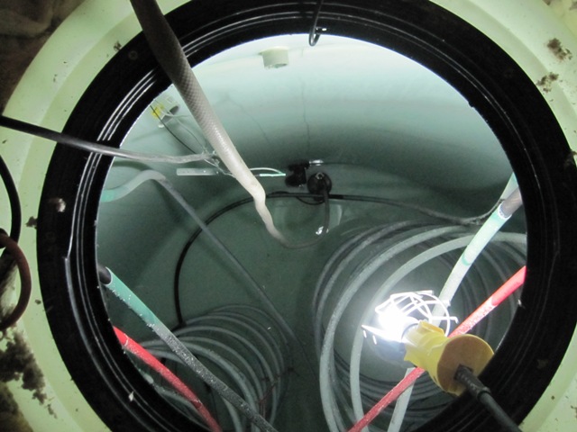
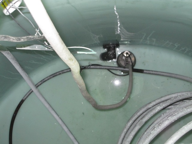
September 17, 2011
Here are some images taken down inside the tank. The copper heat exchanger pipes are covered with dark cupric oxide, which is formed when the copper reacts with oxygen in the water and it actually protects the copper from further corrosion. There are also some white mineral deposits from calcium in the water.


The mineral deposits were especially noticeable near the top of the water level, where they have grown fairly thick and are tinged with blue from copper dissolved in the water. The water tends to be the hottest at the top of the tank, causing the formation of more calcium scale.
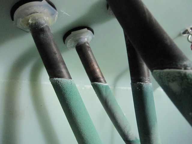
Some problems were immediately evident. After 2 seasons of use, the nylon cable ties used to secure the tubing to the support ropes had become brittle, and about half of them had broken. These were put in place during the tank construction in order to prevent the pipes from rubbing against the ropes causing abrasion of the copper. The pipes are supported using knots every 3rd coil or so, and the knots are still in good shape. The polypropylene rope shows no signs of degradation.
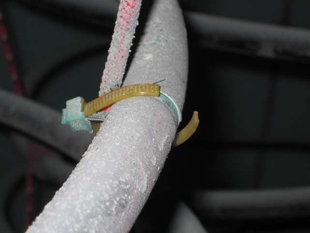
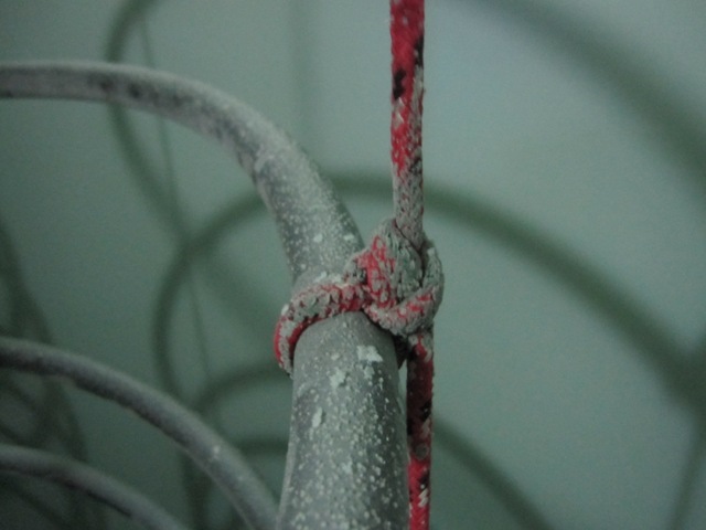
The first photo below shows where one of the coils has shifted, placing it in direct contact with one of the vertical copper tubes leading to the bottom of a coil. Over time this could lead to failure of the tubing at this point, due to abrasion where the tubes touch each other and rub together when the coils move slightly due to changes in fluid flowing through them. This will be easy to fix, by bending the vertical tube out of the way. The second photo below shows one of the PEX tubes that holds a temperature sensor. Originally it was held away from the copper by a nylon cable tie, which has broken allowing the PEX to rub against the copper. This could also lead to failure over time and it will be simple to fix it now.


THE CRACK
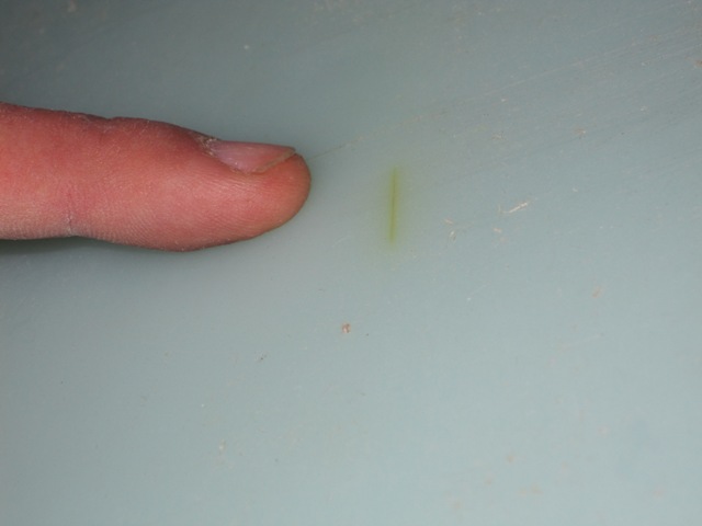
Here at last is what caused all the trouble, or at least we hope this is the only cause! The crack is only about an inch long, and is on the side wall about 8 inches up from the bottom of the tank. It was difficult to photograph well but it’s definitely a crack that extends all the way through the wall. The first photo shows it illuminated from inside the tank and the second photo, also taken inside the tank, is with light shining through from the outside. There is evidence of an impact at this location, as if something hit the wall during manufacturing or transport and caused it to crack, and it is brown-colored as if water has seeped through and left some deposits behind. Apparently it has been there since we installed the tank, gradually increasing in size until it had finally cracked all the way through the wall and let water seep through. Overall the tank does not seem to have gotten brittle from the sustained high temperature (140 degrees F), so this appears to be an isolated problem.

THE REPAIR
Repairing the crack was very simple, compared to all the work of draining the tank and removing the insulation around it. FIrst I drilled small holes at each end of the crack to keep it from propagating any further. Then I ground out a V-shaped channel about halfway through the tank wall, on both the inside and the outside of the tank.

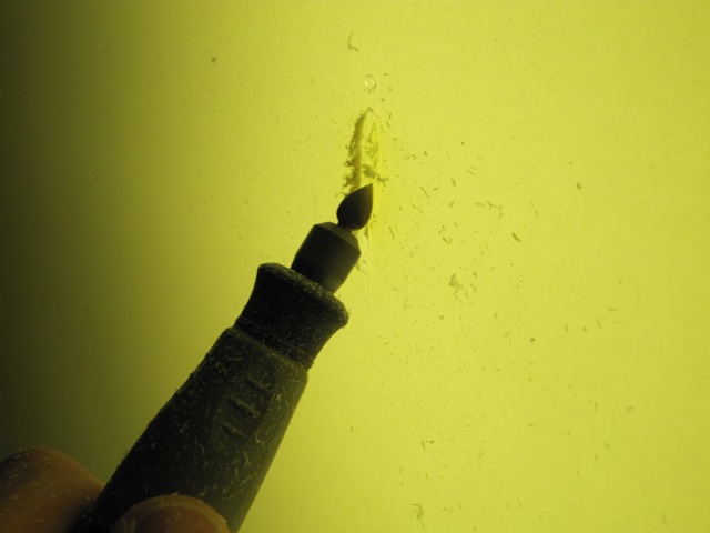
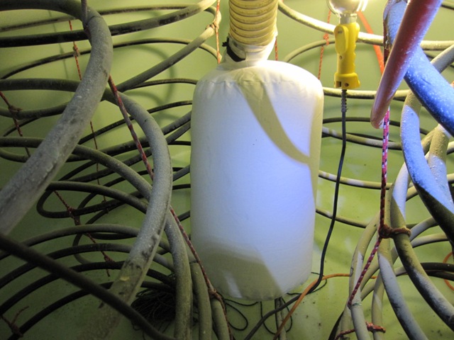
To repair the tank wall I used a Urethane Supply Co. Mini-Weld Model 6 Airless Plastic Welder, Model# 5600HT. It is like a large soldering iron but has a special tip through which a 1/8″ plastic rod is inserted. It comes with a variety of different kinds of plastic rods, and has a temperature control for welding various kinds of plastic including polyethylene which is the material of this tank. The welder melts the plastic rod together with the tank wall, filling the V channel and fusing it all together. It makes a bit of smoke and fumes as it melts the plastic so I used the outlet hose of the insulation blower, together with the filter bag that came with it, to provide a very effective fresh air supply inside the tank. I also wore a respirator with activated carbon filter cartridges so I wouldn’t be breathing any plastic fumes. It wasn’t practical to photograph the welder actually making the weld because it takes two hands (one to hold it and one to feed in the plastic rod), but the second photo shows it starting to heat and soften the tank wall around the V-channel. As soon as it was softened a bit I fed in the plastic rod and started filling in the V-channel I had ground out, and then went back over it all to melt the new plastic together with the tank wall.

I welded the crack both inside the tank and outside. The resulting weld looks ugly because it contains little bits of dark burned plastic that were left on the welder tip from when I tested it earlier. But it is nice and solid, having filled in the V-channel nicely and having fused it all together. It appears very unlikely to leak or crack again in this location.

October 4, 2011
After refilling the repaired tank with 55-degree water from the well, we began warming it up with the solar heat collection system It took about 2 weeks to reach 100 degrees F, and then it leaked again! Fortunately we hadn’t replaced any of the insulation yet, since we were waiting to make sure the repair would hold. Obviously it didn’t, and the photos below show that it’s leaking right through the middle of the crack in two places.

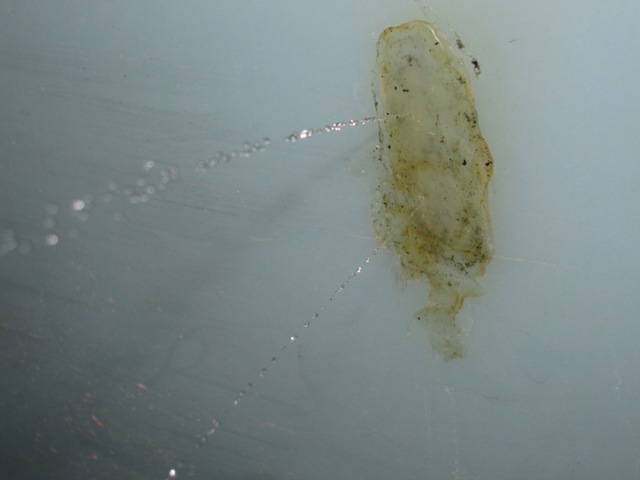
It’s not entirely clear why the repair failed, but a likely cause is that the plastic welding rod that came with the repair kit is made of low-density polyethylene whereas the tank is high-density polyethylene. The difference in chemical composition of the plastics may have prevented them from making a good bond, or it may have made them expand at different rates as the tank warmed up. It’s also possible that the V grooves I carved into the tank just weren’t deep enough, causing stress around the old crack to propagate into the repair material. In order to make a new repair with the same material as the tank, I harvested some plastic from the raised numbers molded onto the side of the tank to indicate the fluid volume. We can’t see them anyway once the tank is insulated, and this should make a better repair.


After grinding out the faulty repair, and creating deeper V grooves on the inside and outside, I melted these numbers back into the crack. I also applied heat to the area longer, to make sure that the repair material was fully melted into and blended with the tank wall. Sorry, no photos of that but visually it looks about the same as it did before.
October 15, 2011
Before refilling the tank, I installed a leak detector to give us an early warning in case it ever leaks again.I ran some speaker wire around the outside of the tank and scraped the insulation off at several points, placing it under the edge of the foam insulation that the tank sits on. I ran the wire out into the utility room, where I connected it to a Reliance Controls THP205 Sump Pump Alarm and Flood Alert. The alarm is quite loud and it should sound the moment any water reaches the wire.


Before replacing the cellulose insulation around the tank, I placed a 6-inch layer of foam packing peanuts around the perimeter of the tank and covered it with some landscape fabric. That way the cellulose should remain at least 6 inches above the bottom of the tank so if we do have a leak this should keep the bulk of the cellulose insulation away from the water. If the foam peanuts ever get wet they won’t degrade and they have enough air spaces to dry out eventually. I also boxed in the area around the repair with some scraps of foam board and filled the box with foam peanuts so that if it leaks in the same area again, I can get to it by cutting a small opening in the adjacent wall. Hopefully it will never leak again but just in case, this should make it possible to repair without removing all that cellulose again!

January 6, 2012
After refilling the tank again and waiting a few weeks with no leakage, I replaced all the cellulose insulation using the insulation blower. It wasn’t practical to take photos during the process but it was pretty much the reverse of removing the material. It went reasonably fast and took about 4 hours. It has now been about 10 weeks since we refilled the tank. The water alarm has remained silent and the repair has held, and we are once again heating the house with stored solar heat.