Cooling System

July 26, 2010
Through most of July we did fairly well keeping the house cool by opening windows at night and closing them up during the day. As long as we could get night-time cooling, the house stayed pretty comfortable even through some very hot weather, due the thermal mass in the floor slab and the super-insulated shell, plus overhangs over the south-facing windows to keep out direct sunlight in the summer. And then allergy season struck with a vengeance! Because our ventilation system has a very high efficiency filter on the air intake, we can keep the indoor air quality quite high and levels of pollen low by keeping the house closed up and running the ventilation system for fresh air. But unfortunately this is at odds with opening all the windows at night to cool down the house – we had to choose between keeping the air clean or keeping the house cool. So we decided to build a cooling system.

A typical whole-house central air conditioner has the capacity to remove anywhere from 3 to 20 kilowatts of heat from a house, and it consumes from 1 to 7 kilowatts of electrical power to do so. So even the smallest whole-house air conditioner takes about 1000 watts of electrical power to operate, and if it runs an average of 8 hours per day it will consume 8 kilowatt-hours of electricity per day. That’s approximately what we have been consuming to run the entire house, so adding a small whole-house air conditioner would double our energy consumption! Because of our extreme level of insulation and other strategies to avoid unwanted heat gain, we could probably get by with just a window-size air conditioner but even that would add at least 50% to our energy consumption. Fortunately, we have a better alternative.

Our cistern contains about 12,000 gallons of rainwater that we have collected, and counting the mass of the cistern’s concrete walls and floor that’s roughly 100,000 pounds of thermal mass. It is currently at a nice cool temperature of 64 degrees F. It has not only a lot of mass, but also a lot of surface area in contact with the earth 10 feet below ground level so it should remain cool even if we add some heat to it. This is a perfect place to dump unwanted heat from the house; all we need is a way to transfer heat from the house into the cistern.

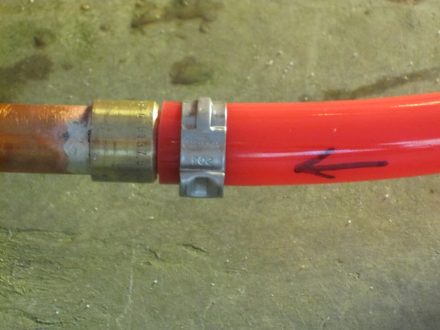
To make a cooling system, we ran two lengths of 5/8″ PEX tubing from the mechanical room to the cistern. At the cistern they are connected to a 60-foot coil of 1/2″ copper tubing. The junctions use soldered-on connectors that join the PEX to the copper.

The heat exchanger coil is placed in the bottom of the cistern where the water is coolest. The water is actually quite clean, but it has some dust floating on the surface that makes it look dirty in the photo below. You can see the copper coil under 8 feet of water. It would probably work a little better to stretch it out more, so it could spread heat over a larger volume of water, but there isn’t much we can do about that without going for a swim.

Once the coil was in place, the other ends of the PEX tubing were connected to the fill/drain hose connections in the hydronic heating (now cooling) system. When the hydronic pumps are running the water circulates down through this heat exchanger in the cistern and then out through the loops in the floor slabs.

We started the system up and let it run for about an hour to stabilize, and then made some measurements to see how it was working. The two pumps are circulating about 2.2 gallons of water per minute on their “medium” speed setting. Water coming out of the floor slabs is at 72 degrees F, which is about the same as the surface temperature of the floors. After it circulates down through the copper coil in the cistern it’s coming back at 65 degrees, a 7 degree temperature drop. This lets us calculate how much heat we’re transferring out of the house and into the cistern: about 7700 BTU/hr or 2,200 watts. This is equivalent to a small window air conditioner, and less than even a small whole-house air conditioning unit if it were running all the time. But we don’t need much cooling capacity because the house doesn’t gain much heat, so it should be enough to keep it cool. We’ll need to run it for a few weeks to see how well it performs in hot weather.

Air conditioning units are given an Energy Efficiency Rating (EER), a number that indicates how efficiently they transfer heat out of a building. The EER is equal to the heat removed in BTU/hr divided by the electricity consumed in watts.  An efficient unit that meets EnergyStar guidelines has an EER of at least 11.5, and the most efficient ground-source heat pump systems have an EER of around 20. At the moment our system is removing 7700 BTU/hr of heat from the house and the pumps are consuming 160 watts, so our EER is 48, which is four times as efficient as an EnergyStar air conditioner and well over twice as efficient as even the best heat pumps available! Unfortunately this is not a steady-state condition, because we are using the 100,000 pounds of thermal mass in the cistern as a heat sink and it is slowly warming up. We won’t be able to measure the true efficiency of the system until it reaches steady-state, where the heat is transferred down into the earth below the cistern at the same rate that we remove it from the floor slab. An educated guess is that the system’s true efficiency will be about half what we’re seeing right now, which is still an EER of 24 and more efficient than any commercially-available cooling system.

Although the numbers above may sound impressive, this is just the beginning of an experiment and we have yet to see how well the system performs in terms of maintaining a comfortable interior temperature during hot weather. We think it will work for us, but only because we need very little cooling capacity in the first place due to the superinsulated structure and our other strategies to avoid unwanted heat gain. And it is only cost effective because we had already constructed the cistern for another purpose and we already had the hydronic system to circulate water through the floors – the added cost of the cooling loop was less than $200 for materials. We’ll post updates here after the system has been running for a while when we can gauge how well it performs.

August 1, 2010
We have beenrunning the cooling system continuously for six days now, and it seems to have reached equilibrium because the temperature in the cistern is holding steady at 66.7 degrees F, which is 3 degrees warmer than when we started. The whole cistern is not at that temperature, just the water in the vicinity of the heat exchanger. As we transfer heat from the house into the cistern water, it warms up a little and transfers the heat down into the earth. When the cistern water’s temperature is no longer changing, then it’s transferring heat into the earth at the same rate we’re removing it from the house, and we should be able to sustain that rate indefinitely.

We switched the pumps down to their lowest speed setting a few days ago, in order to reduce their electricity consumption. That reduced the total cooling capacity of the system a little but it also improved the energy efficiency. So here are the numbers: water coming from the floors measures 73 degrees, and water coming from the cistern measures 68 degrees so its temperature drops 5 degrees as the water flows through the copper tube heat exchanger in the bottom of the cistern. The pumps are moving 1.8 gallons of water per minute on their low setting (where they each consume only 60 watts), which means the system is removing about 4100 BTU/hr (1200 watts) of heat from the house. That gives us an EER of 34, about 3 times as efficient as a good air conditioner and nearly 2 times as efficient as a good heat pump system! More importantly, the house is staying comfortable at 75 degrees or less despite outdoor temps in the upper 80s. We’re using 2.9 kW h of electricity per day to run the circulating pumps, which is significant when our typical usage is around 10 kW h per day, but we would only expect to run this system about 60 days per year so the cooling load represents only about 2.5% of the annual energy production from our solar electric system. To put it another way, our cooling system will consume as much electrical energy in an entire season as a large central air conditioner system consumes in one day!

June 15, 2012
Continued: Enhanced Cooling System

East Bath Countertop

July 18, 2010
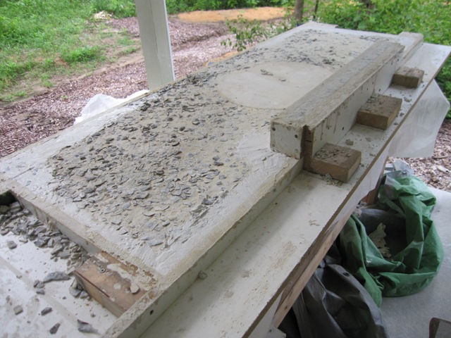
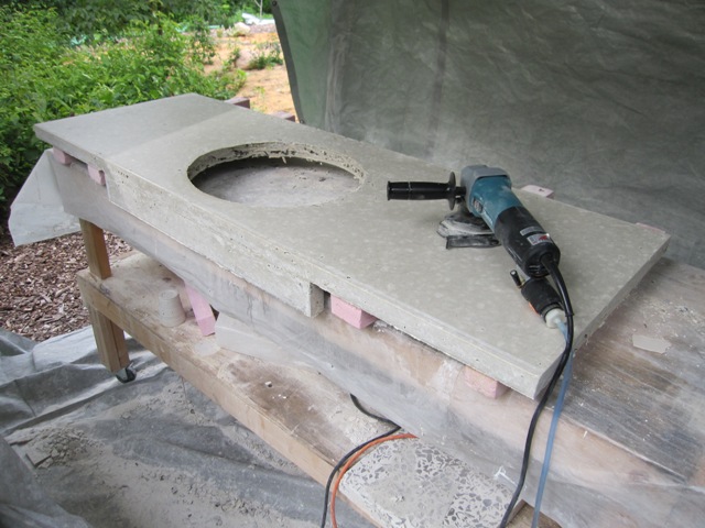
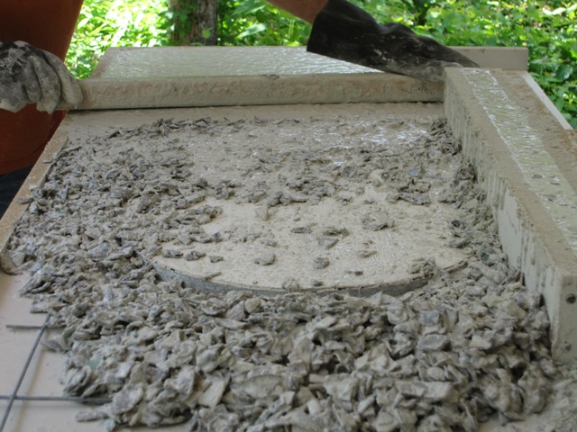
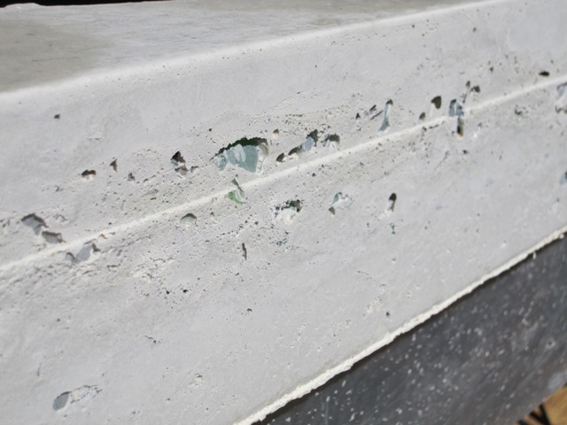
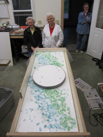
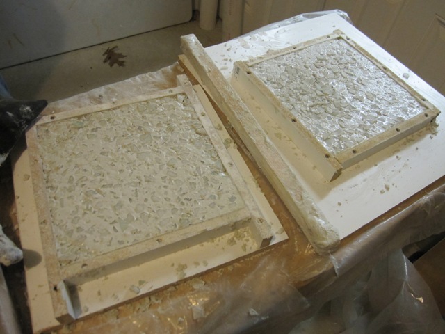
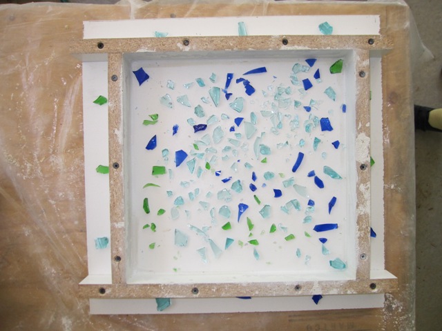
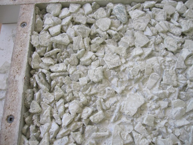
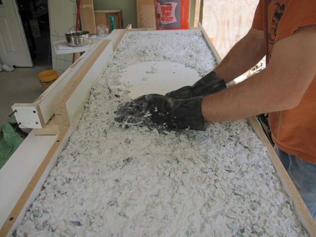
We cast the countertop for the third and final bathroom in basically the same way as the middle bath countertop. The photos below show the countertop in its mold, and you can see that the exposed surface (which will be the bottom) is pretty rough. For some reason it was hard to smooth out the surface and we ended up with a lot of glass chips exposed. This should not hurt anything but we’ll have to grind this surface down a bit so that it sits solidly on the base cabinets. As with the middle bath, we used clear and colored glass for the first layer (which will be the top) and then we used all brown glass for the second layer that won’t show. The first layer ended up a bit stiff, with less water than the previous time, so we expect to have some some bubbles that will need filling. It wasn’t as stiff as when we poured the cottage bath countertop though, so hopefully it won’t be too bad.

July 22, 2010
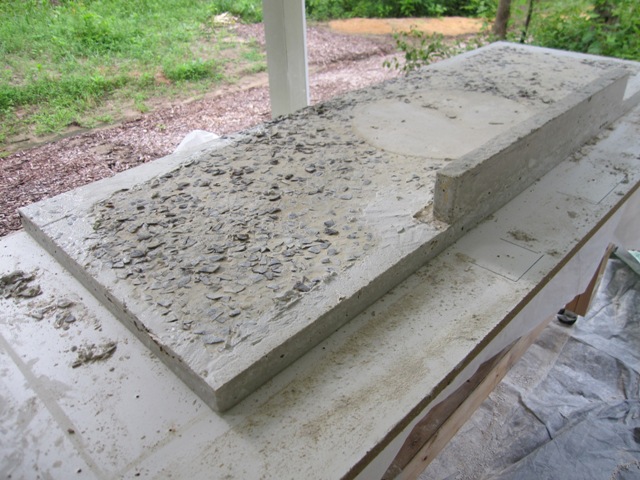
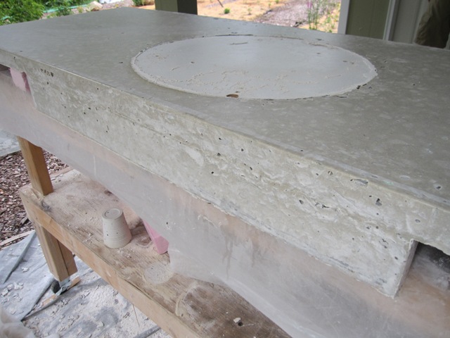
After letting it cure for 4 days, we removed the sides of the mold. In the second photo below you can see that theĀ  front apron has some voids from bubbles in the concrete, more so that the last countertop when we used more water in the mix. Overall it doesn’t look too bad though.

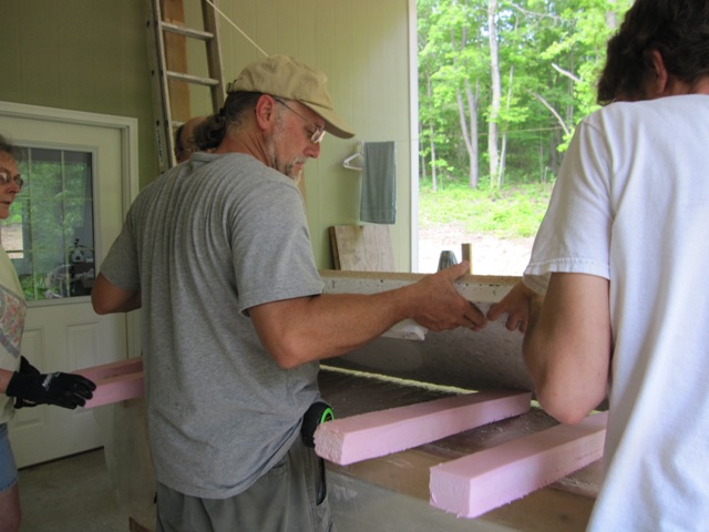
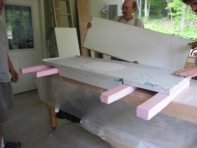
We stood it up on its side and placed foam strips to support it, then lowered it onto the foam. The bottom (now the top) of the mold came off pretty easily, revealing the countertop surface. There are some voids from bubbles in the concrete but they’re not too bad.

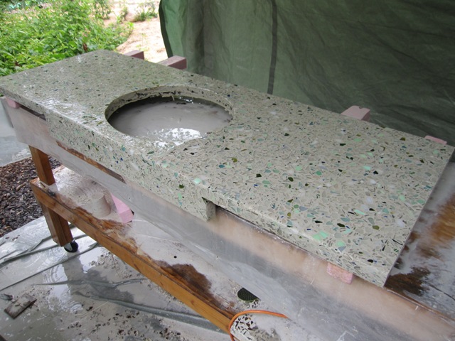
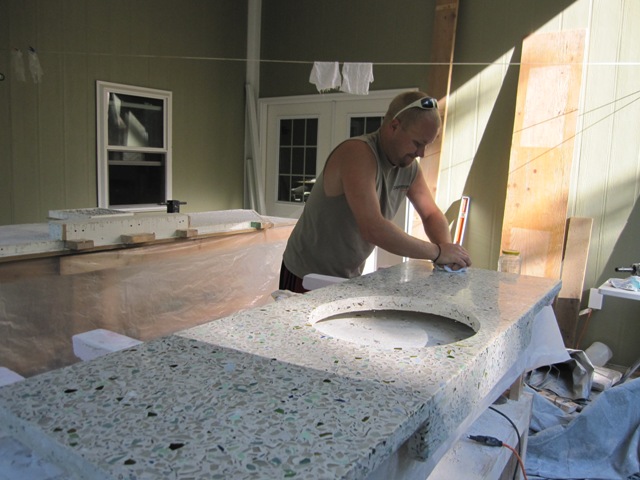
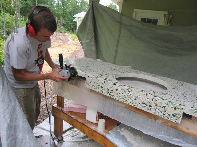
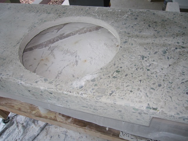
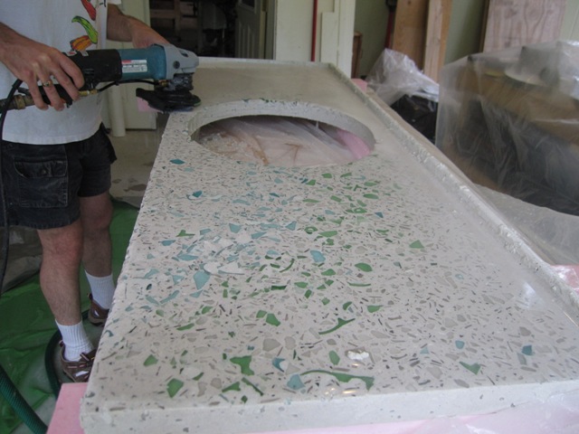
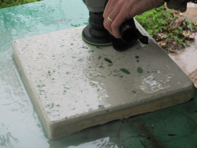
These photos show how it looks before and after the first polishing with the 50-grit diamond wheel. It took about 3 hours to polish it down to this level, and it probably would have gone faster if we hadn’t waited 4 days to polish it because the concrete is already fairly hard.

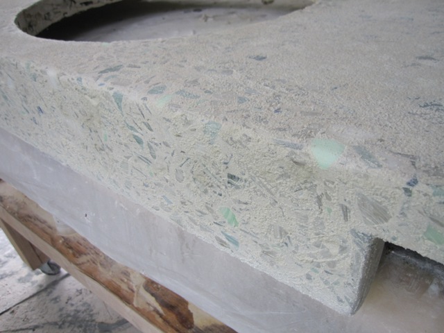
Here are some closer views showing the top and front. If you look closely you can see some voids that will need filling, especially along the upper-left of the front apron.

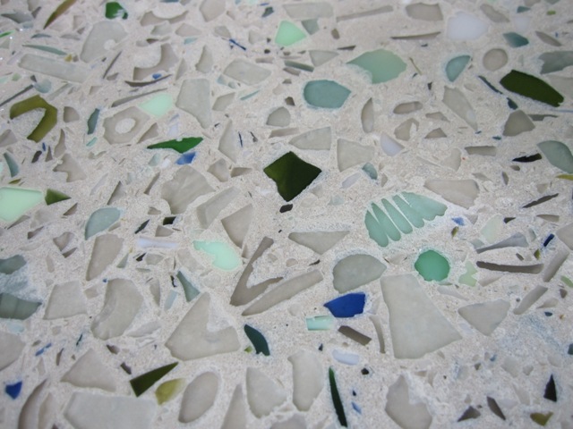
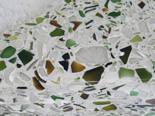
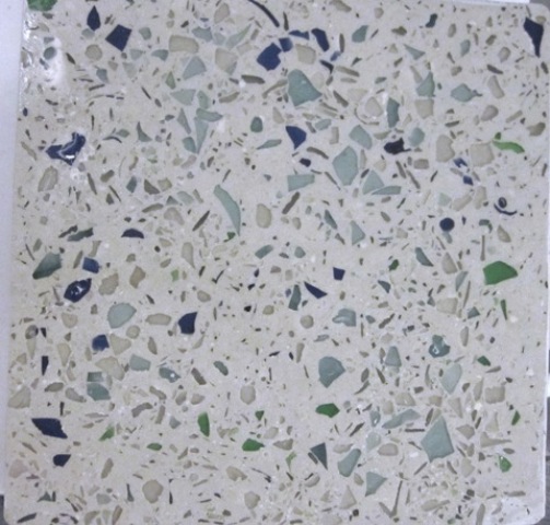
For this countertop we used mostly clear glass, plus mixed shades of green from wine bottles, light green jadite, white, canning jar blue, and a little bit of cobalt blue. One little piece of red glass snuck in somehow, which makes an interesting little detail to the left of the sink cutout.

July 23, 2010
After polishing the whole countertop with the 50-grit diamond disc, there were quite a few voids in the surface from bubbles in the concrete. We covered the whole surface with a slurry made from Portland cement and sand plus water reducing additives, essentially the same mixture as was used to cast the countertop but without any glass and with an acrylic additive to help it bond to the surface. This will fill in most of the voids, and we’ll need to polish it down and then fill any remaining voids with a thin slurry before the final polishing.

July 28, 2010
Polishing down the first slurry coat left a pretty good surface with all of the larger voids filled. The slurry blends in quite well so you can’t see where the voids were unless you know where to look. In the second photo below you can see an interesting pattern from a piece of ribbed jadeite, where the ribs have been polished down somewhat and the slurry fills in between.

There are still some irregularities in the surface as you can see in the first photo below, so we applied a smooth slurry to fill them in.

August 14, 2010
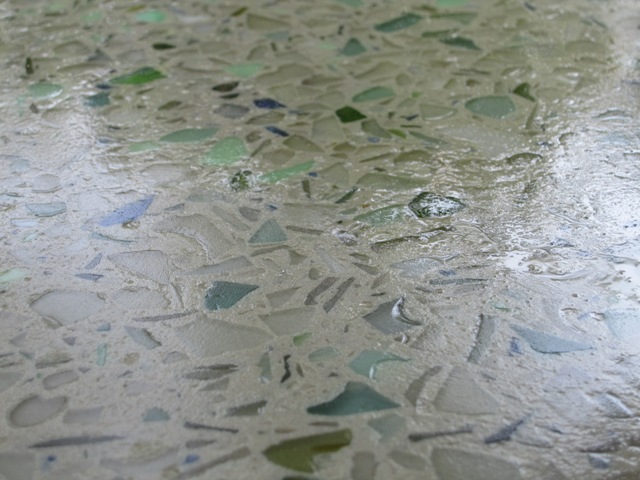
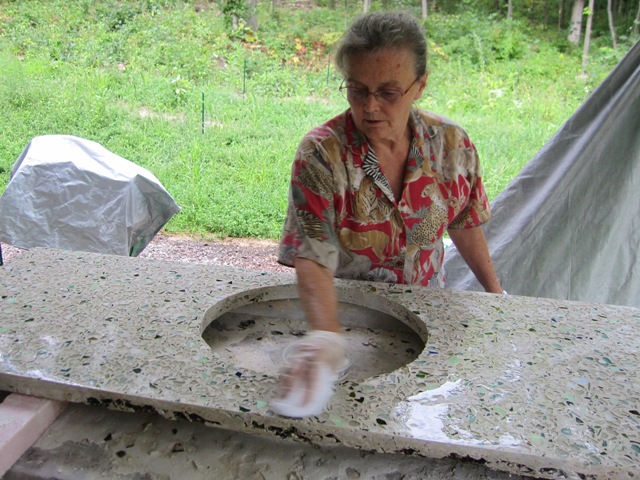
After Jay finished polishing the countertop, Liz applied the sealer. The photos below show it still wet, and it won’t be quite as glossy once it dries. After it’s thoroughly dry we’ll apply a coat of wax and then it’s ready to install.

August 16, 2010
Our nephew Nash applied a thin coat of concrete countertop wax and then buffed it to a nice glossy shine.

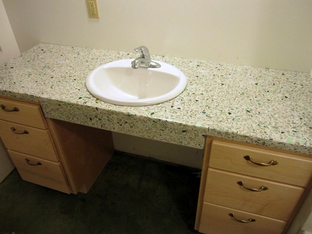
After it was waxed, we moved it into the east bath and set it on the base cabinets, after running a bead of silicone caulk along the left and right edges of each cabinet. The caulk will adhere the countertop to the cabinets but it can be removed if it ever becomes necessary.

Here are some closer views of the left side and the apron in front of the sink.

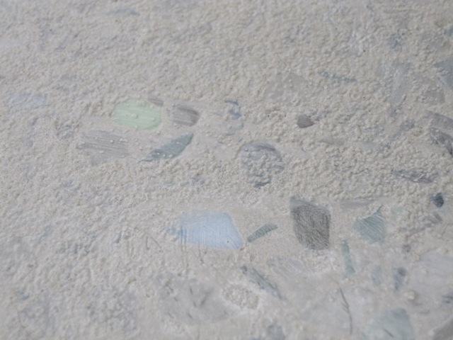
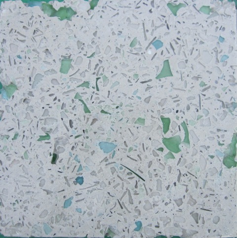
These close-ups show the texture of the glass in the finished countertop. The toothy white shape on the right looks like it came from an old white glass canning jar lid that had serrations around the top. Overall we’re happy with the way it turned out.

Middle Bath Countertop

Includes affiliate links that help offset our expenses at no cost to you. Affiliate programs and affiliations include Amazon Associates and the eBay Partner Network.

June 18, 2010
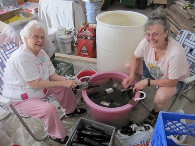
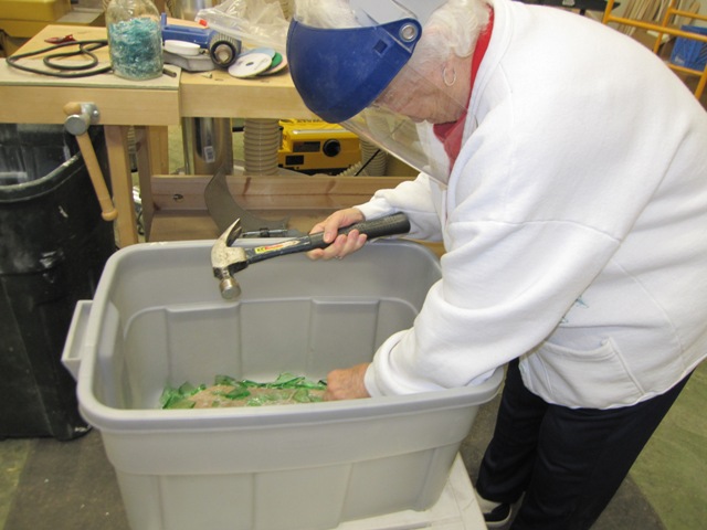
Withour supply of recycled glass running low, we paid a visit to the nice folks at Schmohz Brewery who were kind enough to donate five barrels of beer bottles that customers had returned for deposit. Michigan has a mandatory 10-cent deposit on beer bottles and because Schmohz is a micro-brewery, it’s not economical for them to clean and reuse the returned bottles so they normally send them to a waste facility. From there they may get recycled but are usually just placed in a landfill because the price of scrap glass cullet is very low these days.  Pat and Liz set about washing them up and removing the labels, a big job! Then we ran them through the glass crusher.

June 26, 2010
With the success of our first countertop, we moved on to the one for the middle bath. This countertop is a little bigger and otherwise very similar to the first one, but we decided to use a different technique. We mixed the concrete in two batches, with the first batch containing roughly 65% clear glass, 30% green glass (mostly from wine bottles), and 5% brown glass. This layer will become the visible surface and it should be mostly white/clear, with a fair amount of mixed shades of green and just a bit of brown and amber sprinkled through. The second layer, which won’t be visible, will be all brown glass since we have so much of it now.

With less concrete per load, it was easier to mix up compared to the first countertop when we did it all in one batch.

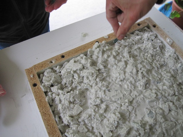
After it was mixed, Jay spread the first layer in the mold to fill it about halfway up. We mixed this batch a bit more runny than last time, in hopes that it would leave fewer air bubbles on the bottom (which will become the top).

We also tried a new technique with the concrete vibrator, with a wooden block attached to let us get down into the concrete better. It seemed to work pretty well and released a lot of air.

This time we decided to put steel reinforcing mesh into the countertop, to strengthen it. The first countertop worked okay without it but this is a little extra insurance against cracking. We placed it on top of the first layer of concrete, and then attached the “chimney” that will form the dropped apron in front of the sink. The chimney is filled with the same concrete mix as the first layer. We also mounded this mixture against the front of the mold so the second layer won’t show.

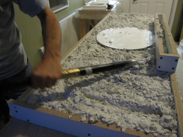
Once the mesh was in place, we mixed the second batch of concrete containing all brown glass. After it was placed over the reinforcing mesh, Jay screeded it off to make a level surface. Once it was all in place, we covered the mold with plastic to keep it from drying out too rapidly. It will need to cure for about 4 days before we can take it out of the mold.

June 30, 2010
We removed the countertop from the mold after curing it for 4 days. The top surface looked very good, with almost no voids. This is a big improvement over our first countertop, and we attribute it to having a wetter mix plus more vibration to release trapped air, and to mixing all of the colored glass into the first concrete pour rather than placing the colored glass directly into the mold before pouring.

The apron in front of the sink was not so pretty, with quite a few voids that need to be filled. In the second photo below you can see that the top (first) layer is quite solid, but the material that was placed in the chimney afterward did not consolidate well. The mixture was getting stiff by the time we placed it, and it was hard to vibrate the chimney section to release trapped air.

We ground off the surface with the 50-grit wheel to expose the glass and the colors look very good. Once we had ground it down to expose the glass all over, we filled the surface with a slurry of Portland cement and sand over the entire countertop, to fill in the large voids in front and also to fill small voids from bubbles on the top.

July 6, 2010
After the first coat of sand slurry was well cured, it was time to polish it down again. Our nephew Josh did the polishing with the 50-grit diamond wheel, and the result looks really good with just some minor voids still to be filled. We’re really pleased with how the colors turned out.

July 7, 2010
After polishing the surface with the 100-grit diamond wheel, we applied a slurry of just Portland cement with no sand this time. This filled in all the small voids in the surface. Now we’ll cover it in plastic to keep it from drying out too fast, and let it cure for several days so it’s hard enough for the final polishing.

July 11, 2010
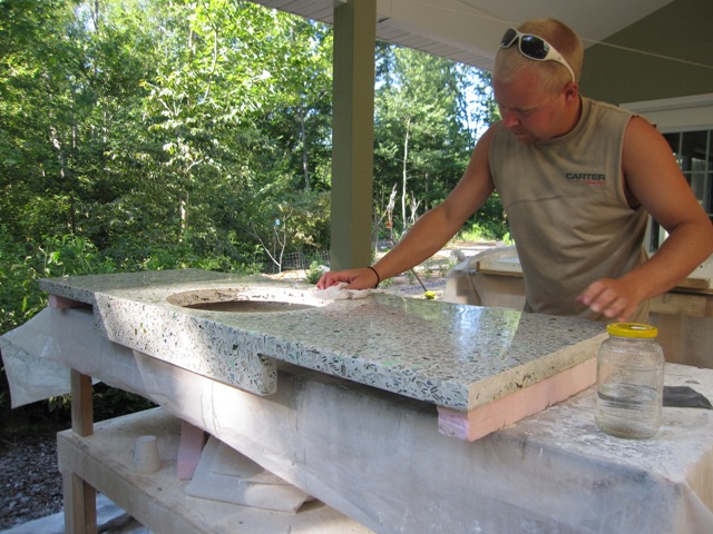
Jay polished down the last slurry coat, and then continued to polish using successively finer diamond discs up to 800 grit. It took about 5 hours of polishing, most of which was grinding down the slurry coat with the 100-grit disc. This photo shows the countertop all polished, just wet with water and not sealed yet.

Here’s a close-up of the surface, where you can see the “teeth” from around the bottom of a brown beer bottle. The second photo shows a closer view near the sink cut-out. The sunburst pattern in the clear piece near the middle of the photo is on the bottom of the glass; the top is polished smooth so you can see through to the bottom. This was from the bottom of some jar or drinking glass and it came out of the crusher this way. We glued this piece of glass into the mold so it would stay put while we poured the concrete over it.

July 11, 2010
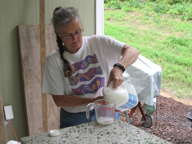
Liz sealed the countertop using Cheng concrete countertop sealer. It’s a water-based acrylic sealer and the first coat starts out at half strength, cut 50% with water. The concentration is gradually increased over several minutes until it’s being applied full strength. After half an hour a second, full-strength coat is applied. Then it has to dry overnight before waxing with concrete countertop wax.

July 14, 2010
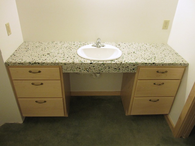
Today we finally installed the countertop into the middle bath. It was a bit of a challenge to muscle it into place since it weighs about 200 pounds, but we managed with only a few paint scrapes on the wall. Fortunately it is the right size! As we did with the first countertop, we ran a thick bead of silicone caulk around the top edges of the cabinets before setting the countertop into place so that it will be supported all around.

Cottage Bath Countertop

Includes affiliate links that help offset our expenses at no cost to you. Affiliate programs and affiliations include Amazon Associates and the eBay Partner Network.

May 17, 2010
After doing three test pieces we decided we were ready to try making an actual countertop. Jay’s mom Pat crushed up some pale green glass to add to the blue canning jar that Peggy had crushed a few days ago. Jay made the mold from melamine, with an oval block in the center for the sink cut-out. We spread the blue and green glass into the mold in wide diagonal bands.

May 20, 2010
After the glass was placed in the mold, Jay added a “chimney” that will form a dropped apron in front of the sink (keep in mind that it’s upside-down at this point). We wheeled it out onto the lanai for the pouring operation.

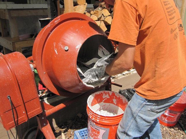
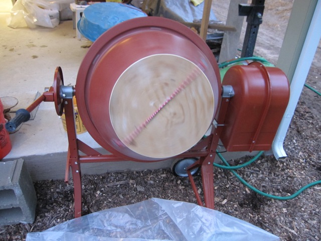
The countertop takes a little over a cubic foot of concrete, which is hard to mix in a small cement mixer like this without some of it spilling out the front. So Jay added a plywood cover that lets us mix a little more concrete, and also keeps in the dust while mixing the dry ingredients. After weighing out the sand, glass, Portland cement and additives, we mixed it all together without water for about 5 minutes.

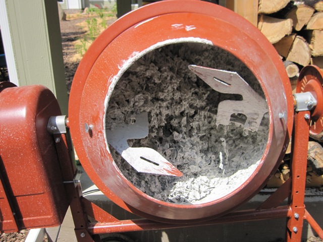
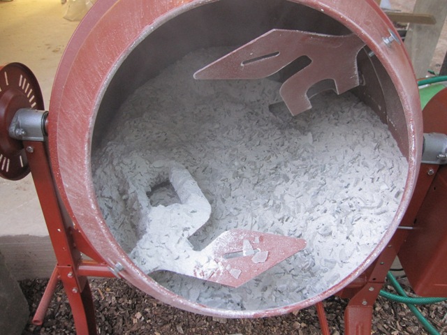
Here’s a close-up of the dry mixed material. You can see some of the polypropylene fibers sticking out from the mixer blade. We’re not using steel rebar in this countertop so the fibers help strengthen the concrete. Individually each one isn’t very strong but with about 6 million individual fibers in a countertop this size the concrete becomes much less likely to crack. The glass chips should also make it stronger than concrete made with gravel, because the chips will overlap to form a layered structure.

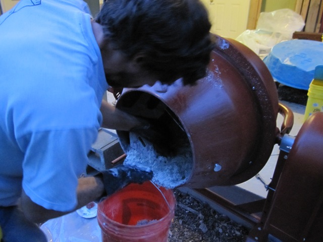
We added the prescribed amount of water and mixed for about 5 minutes, and did a slump test. It’s too stiff to work so we added a bit of water and mixed some more. The second slump test looked about right so Jay scooped the concrete out into a 5-gallon pail.

While spreading the concrete we tried to disturb the colored glass as little as possible. The mix was already getting stiff so there was no problem filling the chimney and having it stay put. The hard part was working fast enough to get it all placed before it set up. As we added concrete to the chimney Liz placed some colored glass in it so there should be some color showing on the apron in front of the sink.

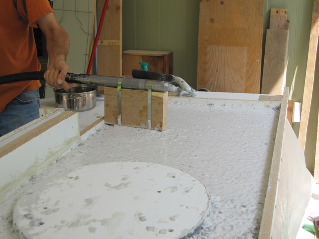
The photo below shows Jay using the concrete vibrator, which is designed to consolidate concrete and vibrates a lot more than the simpler methods we used in our initial tests. This releases trapped air and makes it flow a bit even though the concrete is quite stiff at this point. We vibrated it for several minutes, working the vibrator over the entire surface.

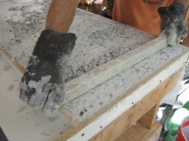
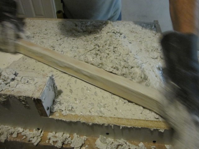
After placing more concrete in the mold we screeded off the top with a board to level it. Fortunately this will be the underside and it won’t show, because it was hard to get it smooth with all the glass in it. The main thing is to get it flat enough to sit solidly on the base cabinets.

Here’s the countertop in the mold, and it seems not too bad for a first try. We had enough extra to fill the two 12-inch test molds, so we’ll have two test tiles to practice diamond-polishing before we polish the actual countertop. Now we need to let it cure undisturbed for 4 days before we can remove it from the mold and start to polish it.

May 24, 2010
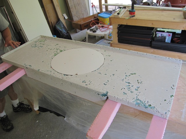
The countertop has cured for 4 days so today we removed it from the mold. It weighs about 200 pounds, which is not too difficult to handle, but the main danger is twisting or dropping it and possibly causing a crack since the cement is not fully cured yet. So we enlisted the help of Jack and Dan to turn it over gently, while Liz positioned foam strips to support it. We could have managed okay with two people but this was good practice for the larger countertops to come.

With the foam strips in place, we carefully flipped it over so that the apron in front of the sink hung over the edge of the workbench.

And finally we removed the bottom of the mold from the top of the counter. It didn’t stick much, so it took only a moderate pull at one corner to get it loose. And with that we revealed the top surface – and a few surprises.

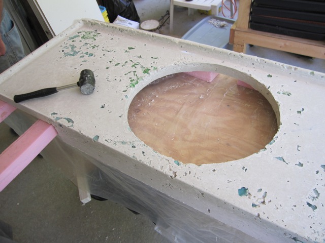
The sink knock-out came out easily, since we had wrapped the edge in 1/8″ foam and duct tape, so a few gentle taps with the rubber mallet eased it out of the hole.

In the photos below you can see the large voids around the areas where we placed the colored glass. Apparently we got the mixture too stiff, and/or we didn’t vibrate it enough to release the trapped air around the colored glass that we placed in the mold. We were hoping to see a solid white surface with glass just below, ready to polish, but this is going to take some fixing!

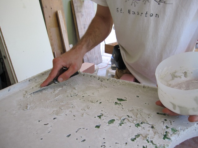
In order to patch the voids, we mixed up a paste of Portland cement and sand, and spackled it into the holes. Once it has hardened we’ll grind it down with the diamond polisher, and then fill any remaining (hopefully small) voids with a slurry of Portland cement and water. It should look reasonably good when we’re done, but it would have been much less work if we could have gotten all the air bubbles out when it was cast.

We also removed the test pieces from their molds, and one of them had voids similar to the countertop so we filled them in the same way. That way we can try polishing it in a couple of days, before polishing the real counter top. The other test piece was better, with relatively few voids, so we polished it a bit to see how the glass will look. The colors are nice, and just about what we wanted for this bathroom, so we’re optimistic that the real countertop will turn out good once the voids are filled.

May 26, 2010
After the voids were patched and the patching material had hardened for two days, it was time to polish it. Jay started out with the 50-grit diamond disc, grinding away the paste on the top surface to expose the glass and rounding over the edges.

It quickly became apparent that polishing the upturned edge at the back was going to be difficult because the diamond pad is not flexible enough to polish the concave curve. For the time being we just left that area unpolished.

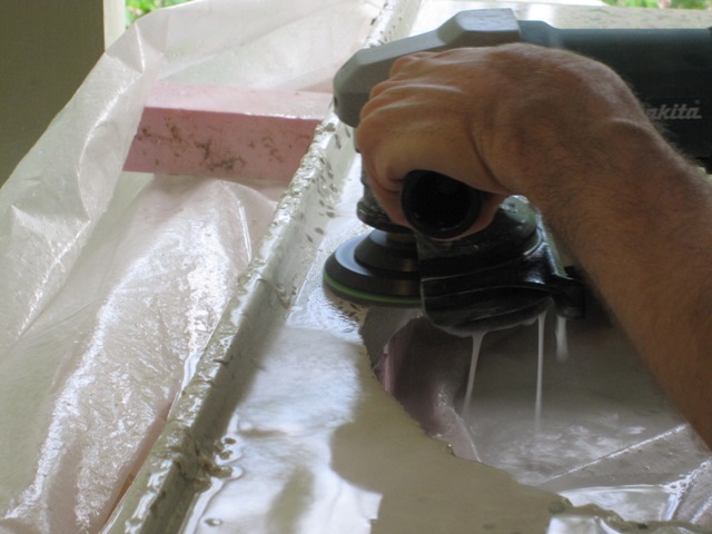
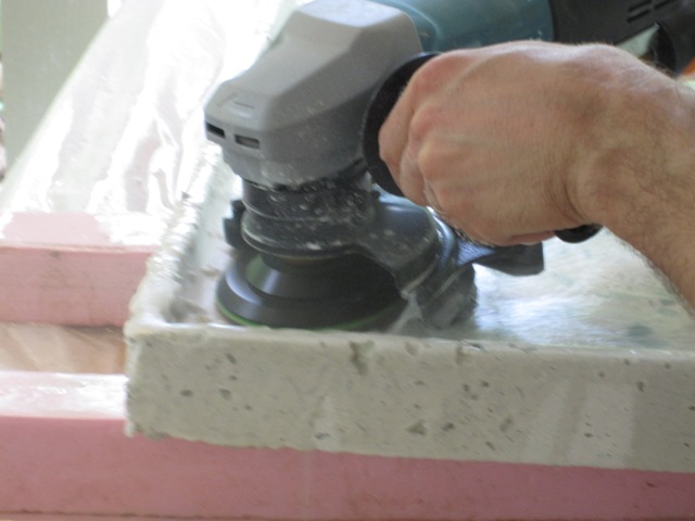
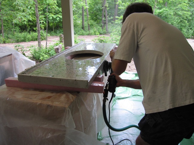
Polishing the sides was not difficult, just a bit messy as the polisher throws a lot of water spray in this orientation.

Here are photos of the countertop after the initial polishing was done. This is only with the 50-grit wheel so the surface is not very smooth yet. We like the colors though, just about what we expected.

Here’s a close-up of the top surface, showing the many small pits caused by bubbles in the concrete. It’s going to take some work to fill all of these.

May 31, 2010
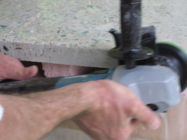
The drip edge on the back of the countertop seemed like a good idea, but it’s just too difficult to polish it with the electric polisher so off it comes! Jay made a plywood spacer a little taller than the height of the countertop on the table, and used it to guide a diamond cut-off wheel to cut off the drip edge. Fortunately it was a breezy day because this dust is very nasty.

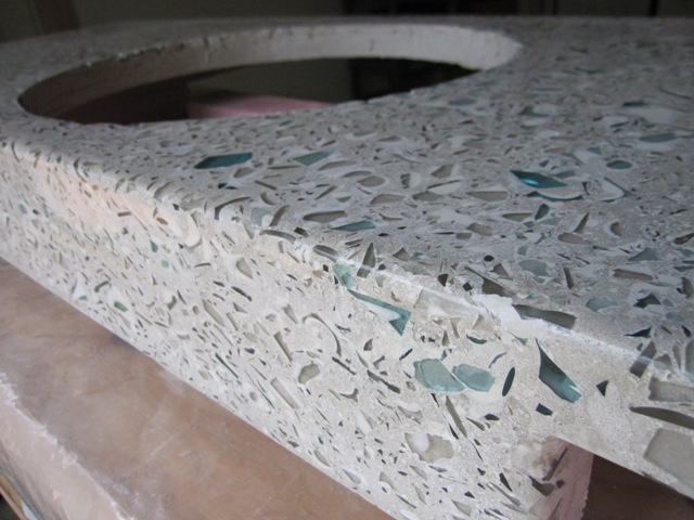
After the edge was cut off, Jay went back and ground it flat with the 50-grit diamond wheel. The photos below show the result. You can see that the glass along the edges was oriented more vertically than on the top surface, which creates an interesting effect. Most of this won’t show however, because we’ll add a tile backsplash along the wall after the countertop is installed.

June 6, 2010
Jay polished the surface using increasingly finer diamond discs up to 800 grit. In order to fill the remaining voids in the surface, he applied a slurry made from just Portland cement and water.

June 8, 2010
After letting the slurry cure for two days, it was polished again with the 800 grit diamond disc. The result looks pretty good, but there are still some small voids in the surface so it will need another coat of slurry and more polishing.

June 16, 2010
It took another coat of slurry and a lot of polishing, but it’s finally done! These photos show the final result, after applying a coat of sealer and wax.

Here’s how it looks overall, and after installation:

Final Grading

May 15, 2010
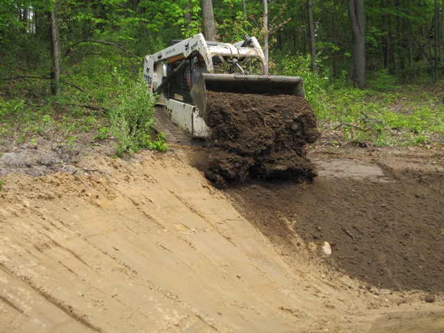
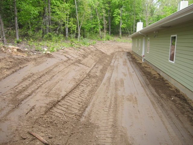
The excavators began the final grading by smoothing out the hillside to the north of the house, and then they spread topsoil over it. They hauled truckload after truckload of the topsoil that we had stockpiled when it was removed during the initial excavation.


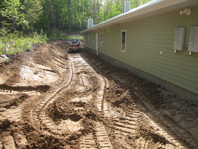
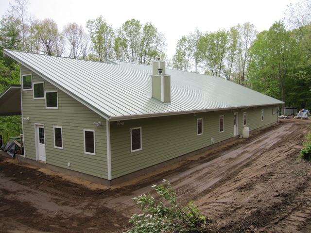
The finished grade in back of the house is gradually sloped to direct all runoff to the east. It drops about a foot from west to east along the back of the house.

The photos below are taken from the northeast corner of the house, showing how the grade directs surface water toward the valley at the southeast corner. The big roof is our rainwater collection surface, which collects about 2000 gallons of water per inch of rain. As soon as the grading was done we hooked up a temporary connection to divert all this water through the cistern overflow drain and into the valley rather than dumping it along the back of the house, to prevent it from washing the topsoil away. Soon we’ll connect the rest of the plumbing so we can store all this water in the cistern.

May 17, 2010
We had a couple of large flat rocks placed right under the roof valleys on the south roof, which is the only roof without gutters. You can see one of them in the second photo below. The rocks are angled away from the house to keep the rainwater from splashing back onto the siding.

These photos show the spreading of topsoil to the south of the house. The topsoil is about a foot deep here, because this will become our main garden area.

May 18, 2010
The grading is now completed. These photos show the main garden area on the south side of the house. We put a 2-foot-wide band of wood chips around the foundation to keep vegetation away from the house. The rest will be planted in a combination of flowers, small fruits, and vegetables.

The first photo below shows the finished driveway, which is now covered with crushed recycled concrete in the area within about 50 feet of the house. This will pack down almost as solidly as a concrete slab but it’s much less expensive and easier to maintain. The second photo below shows the southwest corner of the cottage. All of this bare dirt will be garden space.

Second & Third Countertop Tests

May 14, 2010
The results of the first countertop test were pretty good but we wanted some samples of the colors to be used in the cottage bath countertop. The cottage bath has blues and greens in the decorative shower tile so Peggy broke up some blue bottles and arranged the pieces like this:


The first test seemed a bit too sandy so we tried altering the mix by using half as much sand and correspondingly more crushed glass. The result was quite difficult to work with, and even with relatively little water it fell completely apart in the slump test. There seemed to be too much glass aggregate and not enough mortar paste to hold it together and to fill all the spaces in between.

Since the stuff was already mixed, we went ahead and put it into the mold. It didn’t fill the mold completely, and the top looked more like a gravel driveway than a mass of concrete. Obviously the first mix was better but in order to salvage the test we mixed up some more cement and water and poured it over the top to fill in the gaps.

With the second test not looking promising we went ahead with a third test batch, and this time Peggy put in some red glass to see how it will look.

This time we went back to the original recipe. The first slump test was too stiff so we added water, maybe a little too much as the second time it slumped a lot more. This is no problem for a test piece but it would weaken a real countertop to have that much water in the mix.

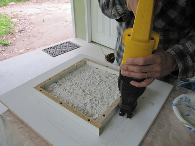
After filling the mold about half full, we tried a new technique for vibrating the mold to release the air bubbles. Using a reciprocating saw with no blade proved quite effective in vibrating the mold, and made air bubbles rise to the surface. With the mold not quite full, we jammed some pieces of colored glass around the edges. Hopefully they will show after the piece is polished.

The full mold was screeded to level the concrete, then vibrated some more to release the remaining air bubbles (we hope).

May 17, 2010
We diamond-polished the test pieces enough to see how the colors will look. Surprisingly the third test piece showed more glass in its surface even though there was less glass in the mixture. Presumably the more liquid mix and the increased vibration allowed more of the glass to settle to the bottom of the mold. Overall we think they both look fairly good, and this will help us choose the colors for the actual countertops.

First Countertop Test

May 9, 2010
Before making our actual countertops, we decided to cast some small pieces in order to test our mixture and our technique. We made a mold 12″ square and 1.5″ high, which is the thickness that our countertops will be. For this test we decided to try placing some colored glass pieces in the bottom of the mold before pouring in a concrete mixture made with just clear glass. We want to use this technique, rather than just mixing the colored glass throughout, because we only have a little bit of some colors like canning-jar blue and we’ll need to use it to maximum effect. This also lets us control, to some degree, the pattern of glass that will appear on the finished countertop.

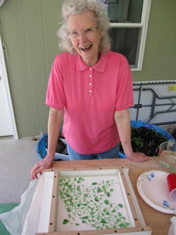
We enlisted Liz’s mom to help smash some green glass pieces for the test. It’s not worth using the glass crusher for such a small quantity, so Peggy just broke it up with a hammer on a large flat rock. Then she carefully arranged the pieces in the mold. We also documented the pattern with a top-down photo (not shown), which we will compare later to the finished piece to see how much the pieces moved around as the concrete was placed. The countertop is molded upside-down, so the glass on the bottom of the mold will end up on the top surface.

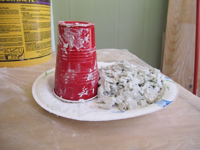
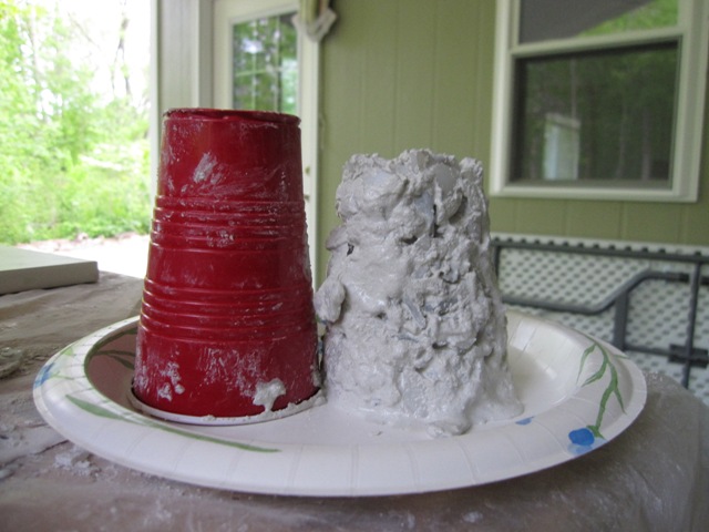
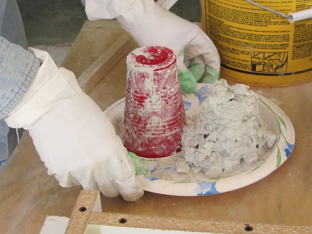
We mixed up the concrete from white Portland cement, crushed clear glass, sand, and a commercial concrete countertop admixture that strengthens the concrete and reduces the amount of water we need. The concrete mixture needs to have just the right amount of water – if it doesn’t have enough water it won’t flow completely and if it has too much water it will be weaker and more likely to shrink and crack. In order to check the water content we performed a slump test using a plastic cup. We filled the cup with concrete, tapped it a few times to settle, cut a small hole in the top to let in air, and pulled the cup straight up. The resulting cone was nearly as high as the cup; it didn’t slump much at all. Too dry!

After adding a little more water and mixing again, we did another slump test. This time the concrete slumped to about 60% of the height of the cup, which should be just about right.

We carefully placed the concrete into the mold, trying not to disturb the green glass. We only filled the mold about half full at this point.

In order to consolidate the concrete and to encourage air bubbles to rise to the surface, Peggy vibrated the mold by tapping around the edges with a hammer.

After tapping for a minute or so, the concrete had settled and air bubbles rose to the surface. If we don’t vibrate it enough, air bubbles will remain and any that are on the bottom of the mold will become pot holes in the top of the concrete (which we can fill later if needed). And we want the liquid to flow around all of the green pieces that we placed in the mold so they’re well embedded in the concrete. But if we vibrate too much, the solids will settle out of the mixture and we could end up with not enough cement “cream” on the bottom to make a hard surface. The photo below shows what we judged to be about right.

With the first layer consolidated, we placed the rest of the concrete and smoothed it with a stick. We calculated the amount of mixture that should just fill the mold and it came up close but a little bit short, partly due to some material still clinging to the bucket and tools. We’ll add about 10% extra next time.

Here’s the finished piece in the mold after a little more vibrating. We’ll cover it with plastic to prevent rapid moisture loss, and leave it undisturbed for 4 days to cure before we remove it from the mold.

May 13, 2010
After letting the piece cure for 4 days, we removed it from the mold. The first photo below shows the piece as it came out of the mold, and the Makita stone polisher we used. The second photo shows the underside of the polisher, and some of the diamond-impregnated polishing discs that attach to it. The first disc on the polisher is the coarsest, 50-grit, which will remove material quickly but leave a rough surface. The other discs have progressively finer grits up to 1500. The stone polisher has a hose connection and a valve so that it can feed water right through its central shaft and onto the piece as it’s being polished.

As Jay started to polish the piece, the green and clear glass started to appear.

After about 10 minutes, most of the green was visible. Overall it took about 15 minutes to polish the top and the edges with the 50-grit diamond disc.

The first photo below shows the green glass as it originally appeared when Peggy arranged it in the bottom of the mold. This photo is a mirror image, so that it can be compared with the view from the other side after polishing. The second photo shows how it looks after polishing with the 50-grit disc. We can see most of the original pattern, but some of the original pieces are not visible – presumably because they moved upward in the mold as the piece was vibrated. More grinding would reveal those pieces but it would also grind away some of the fine pieces of green glass so we won’t grind it any more with the coarse diamond wheel.

Below is a close-up of the two above photos combined, with the original pattern of glass overlaid on top of the final photo. It lets us see how much the green glass moved around as the concrete was placed in the mold, and how much of each piece is actually visible. We can see that most pieces stayed about where they were, but some of them moved by up to 1/2 inch. This tells us that we can create large patterns this way, but there’s no point in placing each piece of glass exactly because they’re going to shift around a bit.

The photos below show how the edges of the piece came out. They look decent but of course there’s no green on the edges and it seems that it would look better to get some colored glass on the edges somehow. We could just mix it all together if we had enough colored glass, and we have plenty of green to do that but not enough of some of the colors we want to use. So instead we’ll try to find a good way to get some colored glass to stay around the edges of the mold.In these photos you can also see quite a bit of texture from the sand that we used in the mix. It seems a bit more sandy than we’d like so we’ll cut back on the sand and increase the percentage of glass for the next batch.

Rainwater Harvesting

Includes affiliate links that help offset our expenses at no cost to you. Affiliate programs and affiliations include Amazon Associates and the eBay Partner Network.

Our rainwater harvesting system is designed to collect and store rainwater for irrigating the gardens and flushing toilets. Originally we had planned to produce potable water with this system using a U-V sterilizer, which is commonly done in many parts of the country and throughout the world. Alas, not in Ionia County Michigan. We were unsuccessful in educating our local code officials in the merits and well-proven safety of using rainwater for domestic needs. It’s just not done in this part of the country because groundwater is abundant and mostly of good quality, so using rainwater is practically unheard-of. This will change, we predict, and when it does we’re likely to see better acceptance of this technology that is already in widespread use in areas of the U.S. where water is not so plentiful. But for now, we use our rainwater only for non-potable needs and draw our domestic water from a conventional well.

The Roof

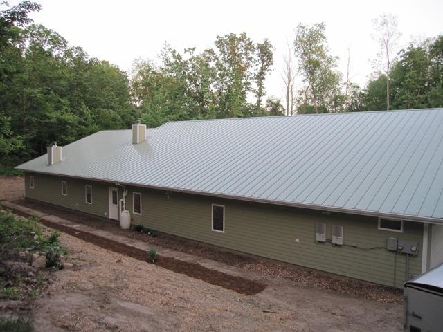
The roofers finished installing the roof in December 2009.The large north roof of the house is the rainwater collection surface, and it represents 53% of the total roof area of the housein terms of horizontal cross-section. It collects approximately 2000 gallons of water per inch of rainfall.
Gutters

April 29, 2010
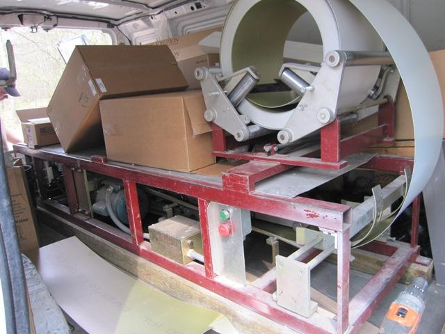
The first photo below shows the machine that produced our seamless aluminum gutters. As the aluminum material unrolls, the machine bends it into the gutter profile and extrudes it out the back of the van.
Here’s a shot of our gutter installer forming one of the two long sections of gutter for the rainwater collection roof. Each section is over 50 feet long, about the longest length that is practical to handle.

We chose Leaf Solution gutter covers to exclude debris as the rainwater is collected. They have a fine stainless steel mesh that excludes even small particles of dirt. Here you can see it shedding maple seeds. This is our first defense against contaminants in the water.

First Flush Diverter

The purpose of a first flush diverter is to discard the first water that comes off the roof during a storm, because this water carries most of the dirt. This is a common approach used in most rainwater harvesting systems. How much water one should discard depends on the size of the roof and how dirty one expects it to be. In our case, with the gutter covers excluding most of the debris, we can get by with discarding the first 50 gallons each time it rains. There are commercially-available first flush diverters that we could buy, but most of them are designed for smaller roofs and don’t handle this much water. For that reason (and because it’s more fun) we decided to design and make our own.

May 20, 2010
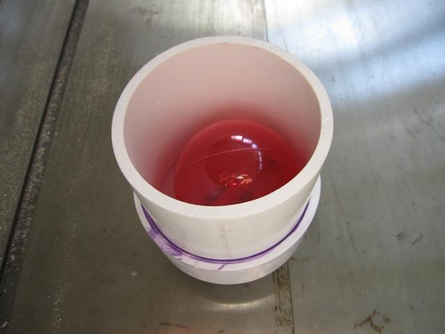
Our design uses a closed 50-gallon barrel to hold the diverted water, and above the barrel is a valve with a floating ball that closes off the incoming water when the barrel is full. This is a common design that we didn’t invent, but here’s how we made ours. It’s made from a pair of 2-inch to 4-inch PVC reducers, a short length of 4-inch PVC pipe, a length of 3/8″ PEX tubing, and a floating ball. The PEX tubing goes in the bottom and will prevent the ball from sealing against the lower reducer. Then the short length of 4-inch pipe is glued in.
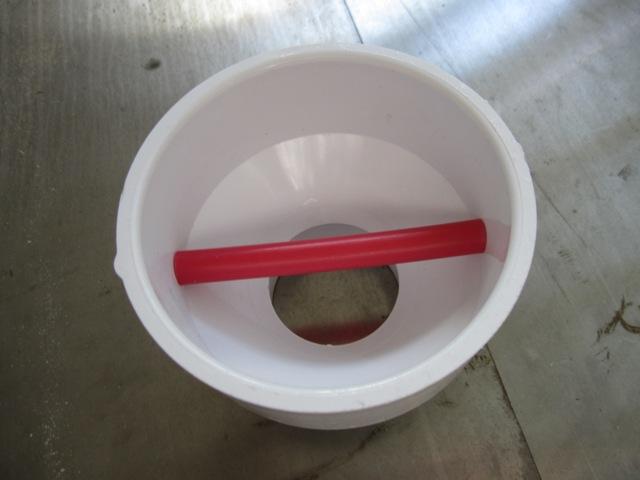
After dropping in the 3-inch-diameter hollow plastic ball, we apply the second reducer to the top. This upper joint is driven tight with a hammer and pinned with a screw but it is not glued so that we can take the device apart if we ever need to service it. Once the barrel fills completely, the water level will cause the ball to float and seal against the upper reducer, closing off the dirty water in the barrel from the cleaner incoming water. Although the inlet and outlet of the floating-ball valve are only 2 inches in diameter, this should be more than enough for the first trickle of water coming off the roof as it starts to rain. Then the main flow of water will pass through 4-inch piping that can handle even a torrential downpour.
Before we could build the rest of the diverter, we needed a solid pad for the barrel to sit on behind the house. This was also a good chance to test out the new cement mixer to make sure it works before we use it to make our countertops. We built a 24-inch-square form and carefully leveled it before pouring the concrete.

May 21, 2010
Getting back to the diverter plumbing, above the floating-ball valve is the Tee fitting that directs rainwater to the cistern after the barrel is full. The shape of the tee may look upside-down, but this is intentional because it prevents any water from running out the side port until the barrel is full. We attached a stainless steel screen inside the tee to prevent any debris from entering the cistern. Although we wouldn’t expect any debris to get through the screen on the gutter covers, they’re not completely sealed around the edges so it’s still possible for insects and some debris to get into the gutters. The screen is our third defense against contaminants in the water, and it also prevents flying insects from entering the cistern via this pipe. Because the screen is vertical in the pipe, it should continually clean itself so we don’t expect to have to clean it, but it will be accessible and replaceable should the need ever arise. This workssimilarly to the commercially-available Leaf Eaterdownspout filter.

May 23, 2010
These photos show the completed first flush diverter. The two gutters at the top deliver rainwater to the 4-inch wye fitting. At first the water passes straight downward through the floating-ball valve and into the barrel (an old pickle barrel with a sealed lid). Once the barrel is full the water backs up through the floating-ball valve and the ball seals it off. Water then flows out the side of the tee fitting and downward into the cistern inlet. Some of the connections are not glued so we can access the internals for maintenance and repair, and there’s a union fitting at the bottom so we can disconnect the barrel for cleaning if needed.
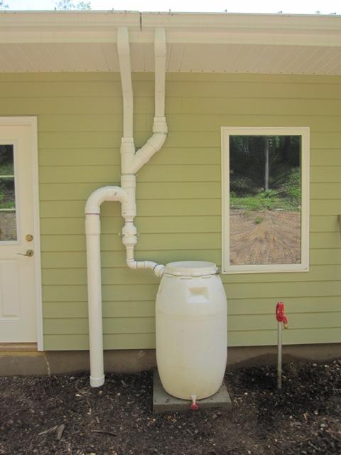
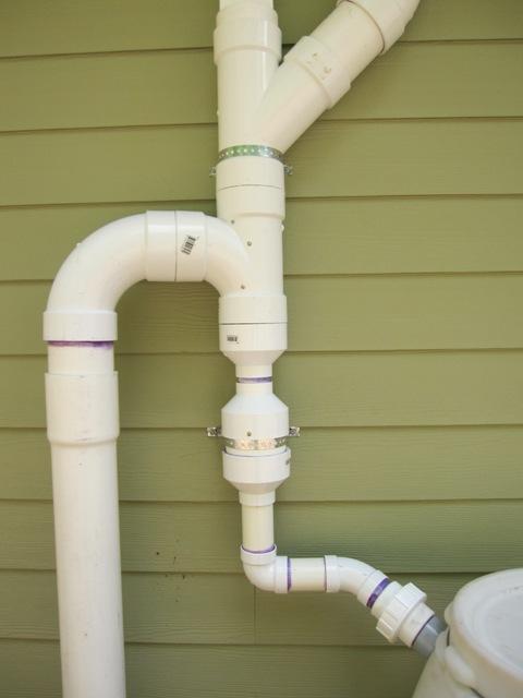
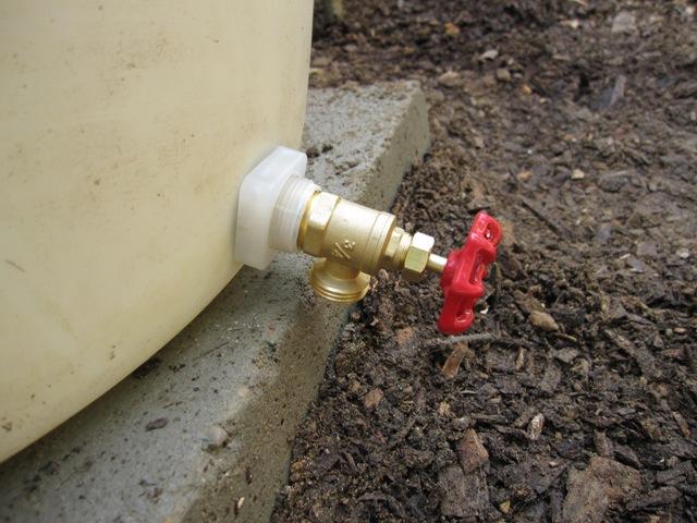
At the bottom of the barrel is a drain valve, which we’ll leave slightly open so that it slowly drains the barrel in between storms.
Calming Inlet

May 23, 2010
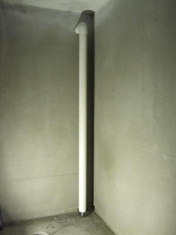
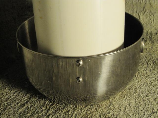
After the water passes through the first flush diverter on the north side of the house, it runs through a 4-inch pipe under the house and into the cistern. We don’t want to just dump water into the cistern, as it would stir up any sediment that had settled out.Instead, the water drops through a pipe to the floor where it hits this ‘calming inlet’, which is simply a stainless-steel mixing bowl screwed to the bottom of the pipe with stainless-steel screws. The pipe stops about 2 inches short of the bottom of the bowl so there’s plenty of clearance for the water to exit. This gently directs the flow of water upward and away from any sediment on the bottom of the cistern.
Floating Filter #1

May 23, 2010
In the first half of the cistern, we built a floating filter that will draw water from just below the surface where it is the cleanest.These are commercially available but we made our own from about $20 worth of parts from Menards.

Update – later on we found an inexpensive ready-made Floating Intake Filter, which would have been a lot less trouble than making our own!

The PEX tubing and fitting are secured with a nylon zip tie into the filter cage, which is half of a screen filter made for pumping water from irrigation ponds. The plastic float is an ordinary toilet float from the plumbing department. The filter bag, also made for the pond screen filter, slips over the whole thing.

The floating filter connects with a length of 3/4″ PEX tubing to the cross connection that we placed into the concrete wall in the middle of the cistern when we poured the concrete. This will allow water to flow slowly from the first half of the cistern into the second, excluding most of the sediment in the process. Many cisterns are built with floating intake filters, but usually only with a single chamber. Having two chambers like this should provide cleaner water as more particulates settle out.

The first photo below shows the connection from the line above heading out of the first chamber, and the second photo shows the other side of the wall where water enters the second chamber. We added the elbow to direct the flow of water upward, to avoid disturbing any sediment on the bottom. This water will flow only by gravity from the first chamber to the second and the flow will be relatively slow due to the 3/4″ diameter pipe, compared to the 4-inch inlet from the roof. Thus the water level in the first chamber will rise during a rain storm, and it may take a few hours for the water levels to equalize.

Pump Intake, Floating Filter #2

In the second (south) half of the cistern, we have another floating filter similar to the first. Any sediment that makes it through the first filtration gets a second chance to settle out in the south half of the cistern before being pumped out. The first photo below shows the pump intake, with a one-way check valve on the right. This prevents the pump from losing its prime by keeping water in the pipe when the pump is off. To prime the pump initially, we need some way to fill this 70-foot-long pipe with water without having to climb down into the cistern. To make this easy, we added the 3/8″ white PEX tube shown at the top of the photo. Both of these tubes will run back to the mechanical room in the house, and we can prime the pump simply by running water into the 3/8″ priming line until the entire water intake pipe and the pump are full. This entire assembly fits into a floating filter bag just like the one shown above, so the pump will draw water from just below the surface where it is the cleanest.

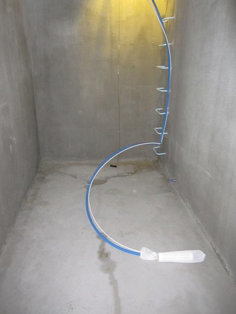
This shows the completed south half of the cistern, with the blue and white PEX tubing leading upward and into the conduit (not shown) that runs to the mechanical room.
Overflow

May 30, 2010
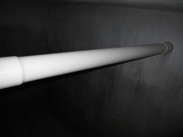
The last piece of plumbing inside the cistern is the overflow, which allows water to flow out of the cistern if it gets completely full. It’s important to screen this opening to prevent pests such as insects and rodents from entering the cistern. After all, a dead rat would not benefit our water quality! We don’t have to worry about lizards in Michigan but in some parts of the world they are serious pests of cisterns too. We glued a piece of screen onto a short length of pipe, and inserted it into the overflow fitting in the first (north) half of the cistern. This is where the surge of water will be during a storm so the overflow must come from the first half.

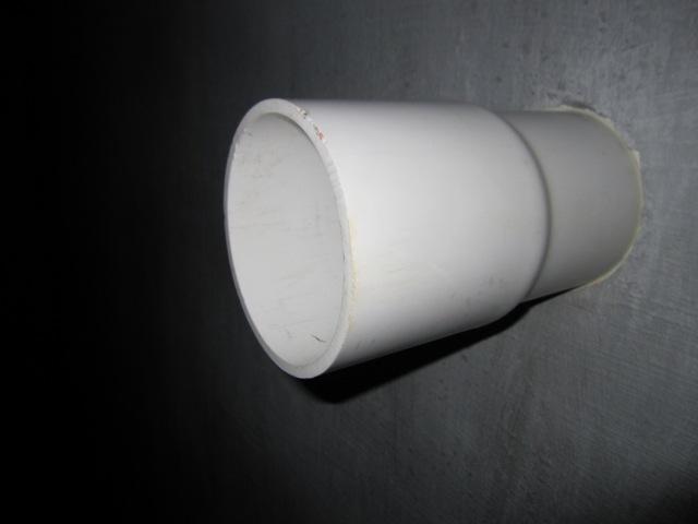
The overflow line passes through the center wall and into the second (south) chamber, and it continues straight through and out the south side of the house just below grade level. From there it runs downhill and into the valley to the south where the buried drain pipe emerges.
First Rain

May 31, 2010
At last we had our first rain storm after hooking up the plumbing.It was not a heavy thunderstorm, just a shower, but we watched as the first-flush diverter barrel began to fill up.

Once the barrel was full, we noticed some leakage around the top as shown in the first photo below. Apparently it’s supposed to have a rubber gasket but it didn’t come with one so we’ll have to fix that. Fortunately the leakage wasn’t a lot compared to the volume of incoming rainwater, so after the barrel filled up water was diverted into the cistern as planned.

June 3, 2010
The first-flush diverter worked pretty well, but the floating filter in the first half of the cistern floated too well! We collected about 2 feet of water in the first half, but the floating filter kept the intake pipe above the water level so none of it flowed into the other half.

To fix the filter problem, we added an elbow to the pipe near the filter basket. We also added a fist-sized rock inside the basket, which you can just barely see in the photo below.

As soon as the modified filter was dropped back into the water, the intake end sank below the surface and water started flowing into the other half.

June 5, 2010
Today we had a thunderstorm that produced fairly heavy rain, and another problem became apparent.When it was raining hard, water started spraying out around the downspout where it enters the PVC piping above the first-flush diverter. This won’t hurt anything immediately, but it’s a serious problem because it would ruin the siding over time and it could cause water damage to the wall. It looks like perhaps the screen filter in the diverter was clogged with debris but we’ll have to disassemble it to be sure. At any rate we need to redesign it a bit so that if an overflow does happen for whatever reason, the water is channeled safely down to the ground without contacting the side of the house. We’ll try to get this fixed before the next heavy rain!
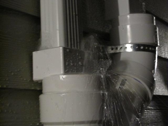
The good news is, even with some unplanned leakage as shown above, we have collected about 3600 gallons of water in the cistern so far.
Deck

April 27, 2010
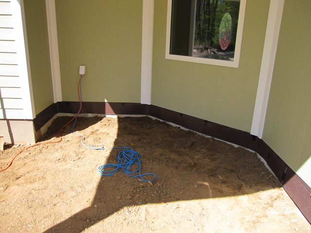
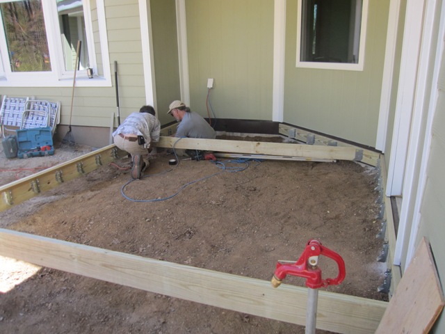
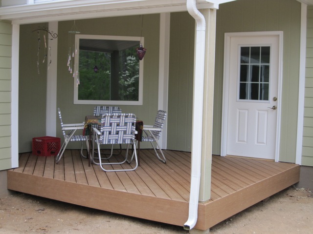
The deck sits under a small roof (about 10′ x 12′) between the cottage and the main house, and is accessed through a door from the entryway. Before anchoring the deck to the foundation wall of the house, we installed metal flashing that will separate the wood from the concrete. Although the wood is treated to prevent decay, the flashing adds an extra measure of protection by preventing moisture from wicking up the concrete foundation and into the wood.

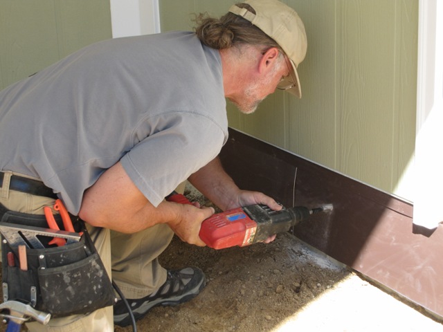
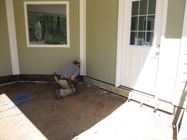
Dan drilled 1/2″ holes through the flashing and into the concrete for anchors to hold the treated ledger board, and attached it after mounting the galvanized joist hangers.

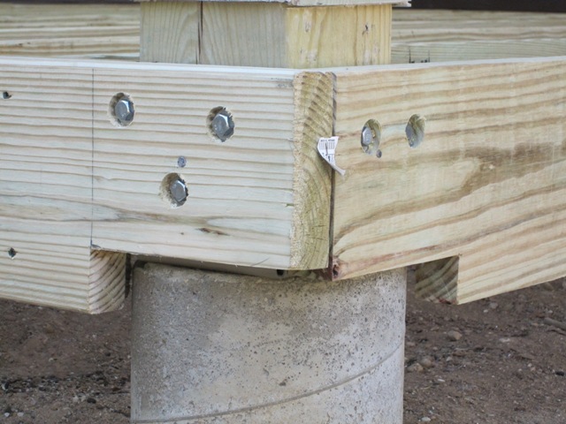
Near the inside house corner, a 2×8 ledger extends to support the front beam of the deck. This connection takes about 1/4 the weight of the deck so we reinforced it well, and we cut the beam to avoid any direct contact between wood and concrete.

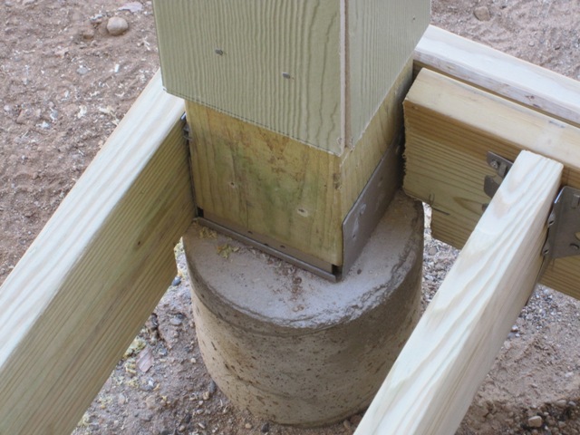
At the front corner, the deck is anchored to the treated post that supports the roof. We notched the boards back to clear the pillar and to avoid any direct contact between wood and concrete. This joint will be covered later so it won’t show.

The first photo below shows the completed structure, and the second shows the flashing detail in front of the door. The door threshold is not installed yet. The deck will sit at the same level as the main house floor so there’s no step when going in and out, just a small bump where the door threshold is raised to meet the door’s weatherstripping.
April 28, 2010
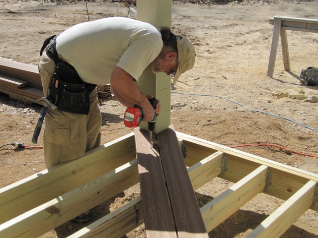
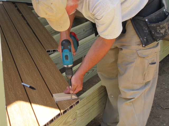
We chose a diagonal pattern for the deck boards, which actually saves a little decking material because we can use the cutoffs more efficiently, but it takes a few more floor joists because they need to be 12″ on center in order to support the diagonal decking. Running the boards straight across would have been easier but we think this looks much nicer. We chose UltraDeck composite decking material, which is made from 50-60% recycled wood fiber (a mixture of post-consumer and post-industrial) and plastic resin that has a varying recycled content depending on availability. The deck boards are spaced 3/16″ apart and secured with matching triple-coated screws.

According to the manufacturer, the UltraDeck Hollow profile uses 43% less material to manufacture compared to solid decking, and also requires 37% less energy to produce and 41% less energy to transport. Because the open ends are exposed, we cut them flush with the wood in order to cover them with cladding material. The cladding is the same material as the deck boards, but only 7/16″ thick and it comes in planks 10.5″ wide by 12′ long.

Here’s the finished deck with the cladding installed. The gap between the cladding and the dirt will be filled with pea gravel to keep varmints out without wicking moisture up to the structure.

Thermal Images

March 23, 2010
Our LEED green rater came this morning in order to take some thermal images inside the house, using a special infrared camera that can measure subtle temperature differences. The goal is to pinpoint areas of abnormal heat loss so that we can remedy them if possible. In each of the image pairs below, the first shows an ordinary visible-light image and the second is the color-enhanced infrared image of the same area. In the infrared images, warmer areas are shown in shades of orange and cooler areas are shown in shades of blue. These were taken with two different cameras so the perspective is slightly different in some of them, but they show the same general area.

The image below shows the southeast corner of the heated area of the house, with the 16-inch-thick south wall on the right. We can see some evidence of heat loss around the door to the left, but nothing serious. In general the 16-inch-thick wall appears to be evenly insulated and it’s very close to the ambient air temperature except right at the corner where the wall meets the ceiling. We see this pattern in many of these images and we expect that it’s partly due to a little more heat loss through the top plate of the wall, and partly due to a “dead zone” at the corner where the air circulation is reduced.

This shows the top of the walls on the east side of the dining room. We can see significantly more heat loss right at the corners in the dining room compared to the living room wall on the left, and this is expected because the dining room walls are thinner than in the rest of the house. This was a tradeoff we chose to make, in order to set these windows close to the corners to take advantage of the view. It’s a small area so even though they lose a little more heat, overall it’s not very significant. On the ceiling we can see a cool blue area running left to right along the truss that spans this opening, and there was a similar cool area on the other side of the dining room. A check of the attic insulation in this area showed no voids, so we’ll attribute the heat loss to some thermal bridging through the truss above this area. Overall it’s pretty minor though.

Here’s a shot of the floor in the dining room, right below the photo above. As expected we see some cooler temperatures near the corner, where it’s a couple of degrees colder than average.

In the photo below we can see some huge heat loss under the back door. We expected this because the door threshold is just temporary, a piece of plywood with significant air leakage. We expect to tighten this up a great deal when the final door threshold is in place.

This image shows the area underneath one of the bedroom windows. A built-in bookshelf will go into this space. We can see some big heat losses at the bottom, indicating that the green spray foam on the bottom isn’t sealed well to the pink foam board. We’ll make sure to seal this joint well with more spray foam when the bookshelf is installed.

Here’s the window in the main bedroom. We can see some significant heat loss through the fiberglass window frame. It’s a very well-insulated window, but even high-performance windows have significant heat loss. Overall this window has a U-value of about 0.19, which is comparable to 1 inch of pink foam. We can see some additional heat loss near the upper-right corner above the window so we’ll check for an air leak there and make sure it’s sealed well.

The following photo is more interesting than it looks. This wall is between the heat storage tank and a bedroom, and we can see some vertical warm stripes on the wall. These are where the wall studs are, and we’re getting additional heat conduction from the heat storage tank through the studs causing a warm stripe on the wall. It’s only about 1 degree warmer than the surrounding wall but the IR camera is sensitive enough to pick it up.

Here’s another photo in the same room, showing an even warmer stripe near the edge of the door. This heat conduction from the heat storage tank will keep this bedroom a little warmer than the others, which may be fine in the winter and undesirable in the summer. Our heat storage tank design predicts that this will amount to only a few tens of watts so it shouldn’t be a problem.

This image shows the southeast corner of the cottage great room, with the south-facing window on the right. We see a little cool spot right in the corner but nothing that indicates any voids in the insulation. As in most of the other pictures, we think the cool spots near the corners are mainly due to decreased air circulation there.

Here’s a photo of the ceiling in the great room, with the base of a ceiling fan at the bottom of the picture. The noticeable cool spot in the middle is right at a roof truss. We would expect some additional heat loss at each truss location, but this may also indicate that the attic insulation is a bit low in this spot. We’ll check it out next time we’re up in that attic.

Here’s another example showing the foam under a bedroom window, where there are significant cool spots along the joint between the green spray foam and the pink foam board. Clearly this is a weak area where we need to seal better, and fortunately it’s easy to do that now since the built-in bookshelves aren’t yet installed.

The following photo shows the area above the cooktop on the north wall of the cottage kitchen. There’s a suspicious cold band about a foot above the top of the cabinets. Based on the structure of this wall, we can tell that the cellulose insulation must have settled about a foot in this area, because there’s an air barrier right above it inside the wall. Our insulator did not pack the cellulose into the walls anywhere near as densely as we specified, so we had about a foot of settling in most of the walls. In every other area we were able to pack in more insulation from the attic to achieve the required density but this particular spot was not possible to reach from above. We will most likely remedy this problem by blowing in additional cellulose through small holes cut into the wall. We’ll do that from the outside so we don’t fill the house with dust!