Vineyard Update 2013

In 2011 we prepared a vineyard site, put up a deer fence, and planted 40 grape vines along with some raspberries, blackberries, and asparagus. Since we posted the 2012 vineyard update last year, the grapes have continued to do well for the most part. We’ve had a few that died out and had to be replaced but most of the original vines are now in their third year and bearing their first crop.

May 12, 2013
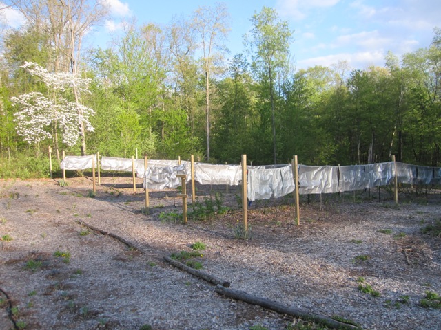
On the night of May 12 we had a late spring hard freeze (28 degrees F) after many of the buds had started growing, and right before the freeze we covered each of the 40 vines with an aluminized polyethylene tarp, clipped at the bottom and sides with clothespins:

The vines still froze pretty hard, enough to kill nearly all of the shoots that had started growing, but they quickly sprouted new shoots from the secondary buds and seem to have done okay. We think the tarps helped, and if a similar situation arises again we’ll use tarps plus drip hoses to keep a flow of water over the vines during a hard freeze.

July 21, 2013

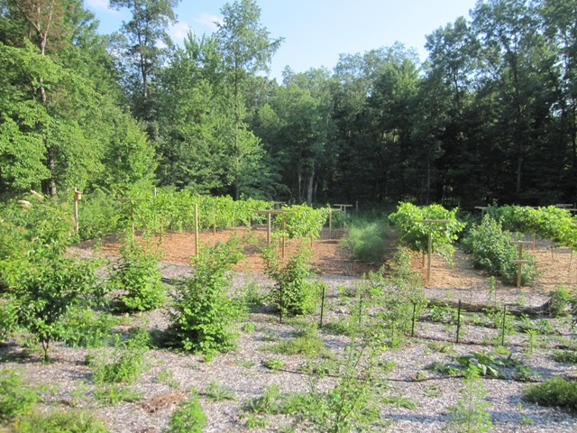
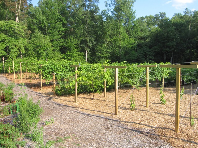
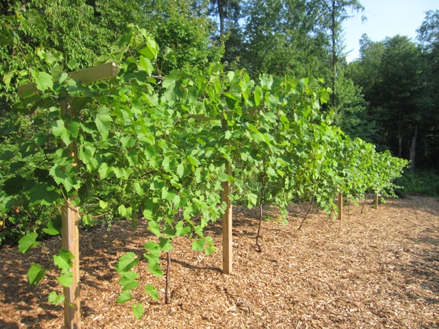
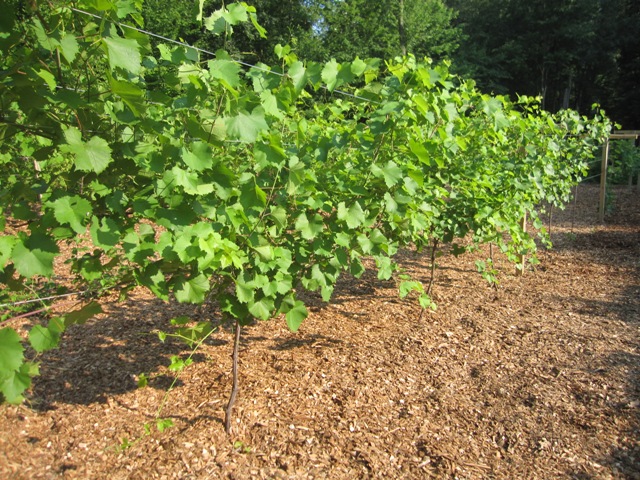
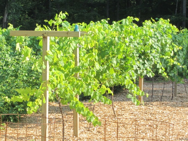
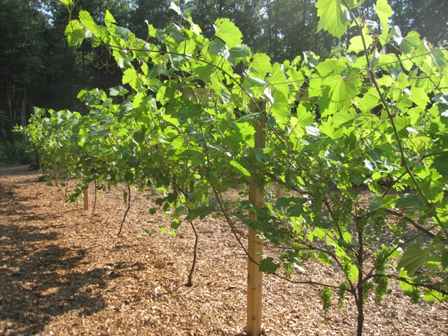
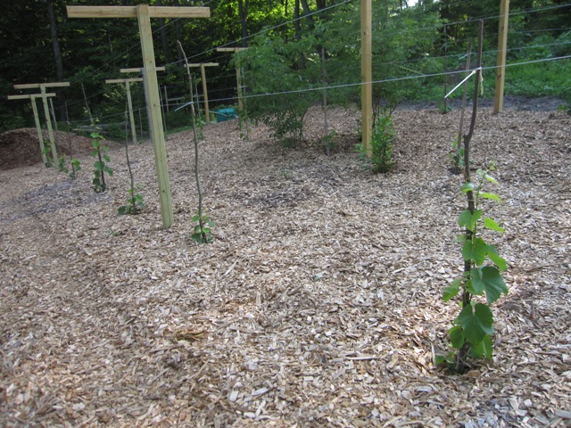
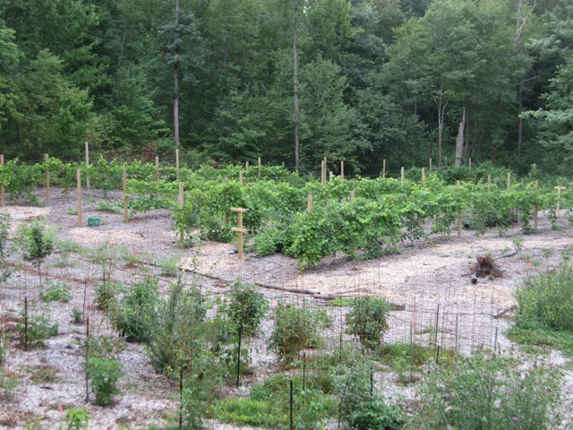
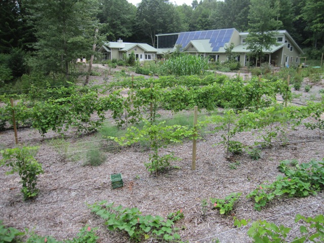
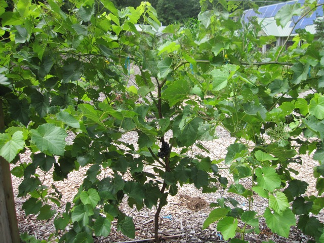
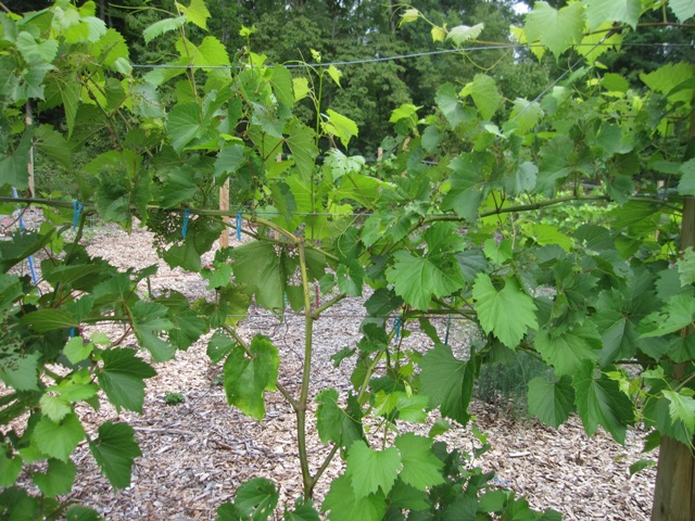
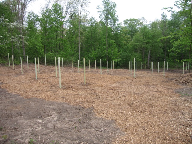
Here’s how the vineyard looks today:

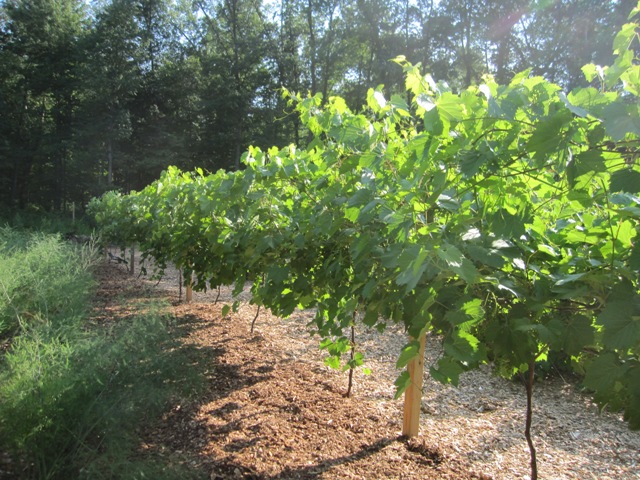
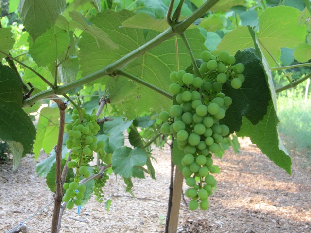
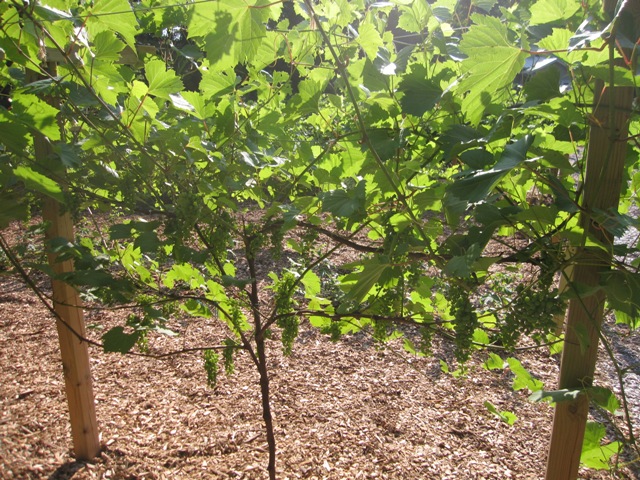
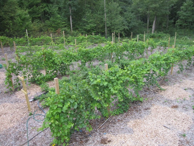
As you can see in the photos above, the mature vines (now in their third year) occupy four rows on the left, each of which holds 10 vines. The newly planted vines are on the right (more about those below). We originally planted 8 vines each of four varieties of wine grapes, plus 2 vines each of four varieties of seedless table grapes. Because this is only their third year, we thinned the flower clusters to one or two per shoot in order reduce the amount of fruit they will set. We’re aiming for 5 – 10 pounds of fruit per vine depending on how vigorous they seem; in subsequent years they should be able to handle about twice that much fruit but we want to avoid over-cropping the vines while they’re still getting established.

Frontenac
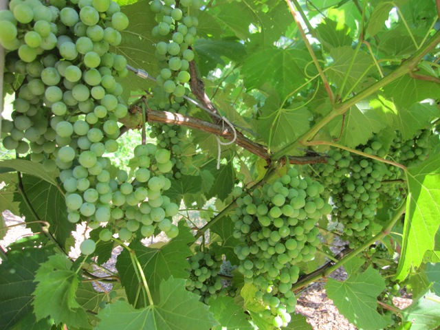
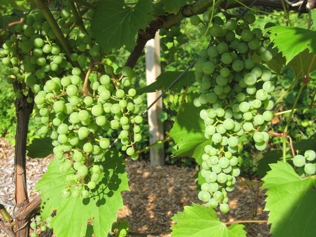
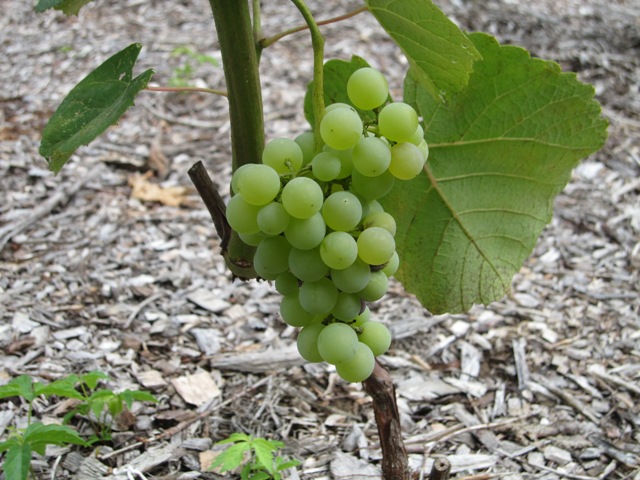
The Frontenac have done really well this year, and seemed to recover quite well from the late freeze. They lost all the shoots that had started to grow, but the secondary buds soon sprouted and bore vigorous shoots with lots of flower clusters that we thinned quite a bit. They have set large fruit clusters, well-filled but still fairly loose, and they seem fairly resistant to fungal diseases. We’ve had to pull a few bad grapes from each vine after early summer rains brought on some black rot fungus but overall it’s been only a minor problem.

Frontenac Gris
The gray-skinned variant of Frontenac (a white wine grape) is growing very similarly, showing good recovery from the late freeze and has set some nice-looking fruit.

Marquette
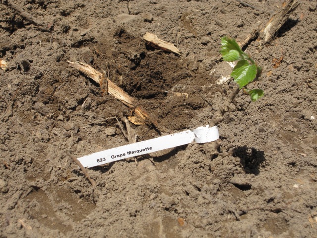
The Marquette was hit the hardest by the late freeze and has been slow to recover. Because the vines were showing weak growth we thinned the flower clusters even more than the other varieties in order to help the vines recover. They seem to be coming back nicely and although the crop is small, the fruit seems to have good quality and little or no fungus problems so far. The fruit clusters are smaller than Frontenac and we tried to keep them to under 5 pounds per vine, considerably less on some vines that seemed slow to recover.

Leon Millot
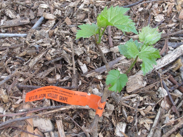
Although the Leon Millot seemed to recover okay from the freeze, the vines are showing signs of stress. As you can see in the first photo below, some of the vines (note the one on the left) have yellowish leaves and we’ve continued to thin the fruit on those vines to help them recover. As the second photo shows, some of the vines are growing well and setting some nice-looking fruit clusters. The clusters are very dense, much more so than the Frontenac and Marquette, which has made it difficult to pick out any bad berries when we find them.

The first photo below shows a Leon Millot cluster with one grape at the top of the lower cluster showing the telltale brown spot of a fungus infection, most likely black rot. Early on it doesn’t look so bad, but eventually the whole berry shrivels and becomes black before releasing spores to spread the infection. We pull the berries as soon as we see any sign of brown spots and so far it’s been only a minor problem. The Leon Millot have shown about the same level of this as the other varieties. The second photo shows how dense some of the Leon Millot clusters are. Next year we may try combing the flower clusters to thin them out so the berries won’t be packed so tightly. At the lower left of the second photo you can see some aerial roots sprouting from the bottom of the cane. This is a common sign of freeze injury, showing that the canes were somewhat injured by the late freeze even though they continue to send out healthy shoots. The aerial roots don’t really cause a problem and we’ll just leave them alone, but they do give us an indication that the vines are stressed so we’ve been reducing the crop load on these vines by cutting out any clusters that don’t look healthy or that have more than a few bad berries. We’re still expecting a modest crop from the Leon Millot this year, perhaps 4 to 5 pounds per vine.

Reliance
Of the four seedless varieties we planted (along with Himrod, Mars and Canadice), the Reliance grapes have done the best. Early on the grapes showed some downy mildew and we culled some entire clusters as well as quite a few individual berries, but the remaining clusters are looking pretty good. The vines got off to a slow start this year, perhaps because of the late freeze, so they didn’t set a lot of fruit but we may get a few pounds from them. More importantly, the vines are looking better now so next year we expect they will do well.

Trellis and Training System
Originally we put in a three-wire trellis with wires at 4, 5 and 6 feet above ground level. This is a little higher than is typical in our region, but getting the grapes higher off the ground makes them easier to work on and tends to get them warmer, which helps them to ripen. Some of our vines are quite vigorous, and they easily produce shoots 10 feet long or more, so keeping them off the ground on the 3-wire trellis was a challenge. This spring we installed two more wires on cross-braces, about 4 feet apart and 7 feet off the ground. This gives us places to tie up the long shoots and keeps the fruit zone more exposed so it’s easier to work on. We are continually tying up shoots with twine, which is a bit of work but it’s enjoyable and it’s better than having to step over shoots on the ground. By spreading the upper canopy over a wider area, we enable the vines to collect more sunshine which should yield healthier vines and better grapes. Plus the increased air circulation around the grapes should help them dry faster in the morning or after rains, to reduce problems with fungal diseases. So far it seems to be working, as we’ve had only minor problems with fungus and we haven’t sprayed with any kind of fungicide. The only spray we have used is Bacillus thuringiensis, a natural biological control for caterpillars that we hope will reduce the incidence of grape berry moth caterpillars. So far we haven’t found any this year but it’s still early.

Below is a view showing the vine structure and how we train them. We are using our own variation of a Kniffen pruning system, which is an old system of grape training that is very common in this part of the country. The only permanent part of the vine will be the central vertical trunk and short renewal spurs (stubs) coming off the trunk just below the wires. Each spring, the vine is cut back to four to six canes that grew the previous year, tied loosely to the wires and cut to have about 10 buds each (the number of buds isn’t crucial and we usually just cut them halfway over to the next vine). Everything else is removed, about 90 percent of the vine! The fruit is borne on the vigorous green shoots that grow from these 4 or 6 arms, and these shoots typically get anywhere from 4 to 8 feet long on our vines, and sometimes even longer. Next year, the cycle repeats and we cut off the old fruiting canes and most of the rest, retaining only the strongest 4 to 6 new canes that originated near the main trunk.

Our variation on the Kniffen system is to add 2 extra wires on cross braces similar to a Geneva Double Curtain trellis, so that we have more places to tie up the shoots as they grow. We don’t try to control them too much, as with the Vertical Shoot Positioning system; we just keep them off the ground and out of our way as we work on the fruit, and try to give them as much space as possible to grow overhead. It’s pretty much a riot of shoots going every which way up there but that’s just fine, as they will all get cut off in the spring anyway. At it’s heart it is still a Kniffen system because we’re removing the horizontal canes every year, which has the advantage of being more resistant to winter injury because they canes are renewed every year. We just spread out the canopy much more than a Kniffen system typically would, by using the extra wires on the cross braces.

New Grapes
This spring we expanded the vineyard with space for 40 more vines by adding three 12-vine rows plus extending the original 4 rows by one vine each into spaces we had originally planned for kiwi vines. So now we have space for a total of 80 grape vines, though we have a few open spaces here and there that we’ll fill in with another seedless variety next spring.

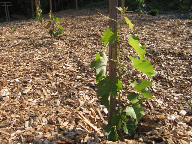
The new cultivars we planted this spring are Traminette, which is a spicy white-wine grape, St. Croix, a red wine variety that has relatively low acid and should blend well with our high-acid Frontenac, and Petite Pearl, an extremely cold-tolerant red wine variety that was recently introduced. The young vines are all doing well and we’ve started training them up stakes:

It’s not strictly necessary to train them up like this in the first year, but we prefer to because it keeps the young shoots off the ground. If they put out good growth that survives the winter well, this will become the trunk of the mature vine. If not, then we’ll cut them to the ground in the spring and train up a vigorous new shoot to become the trunk.

Shed Addition

August 28, 2012
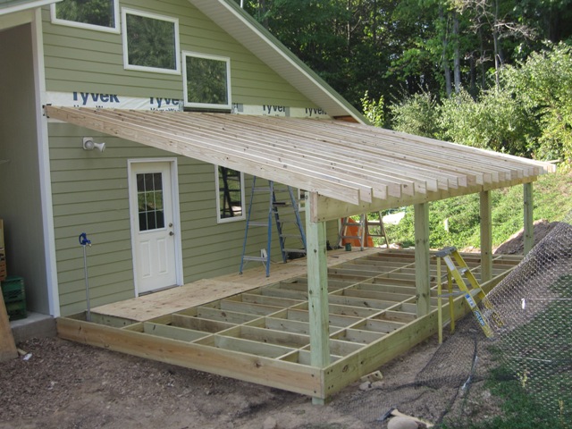
As we’ve expanded the gardens and vineyard we need space to store all our garden equipment, and also a dry place to store our firewood for the winter. So we decided to put a shed addition on the east side of the workshop, where it will be convenient to garden activities and also easily accessible from the shop. It’s going to be a simple structure, 24×14 feet with a deck-like floor and a sloping roof.

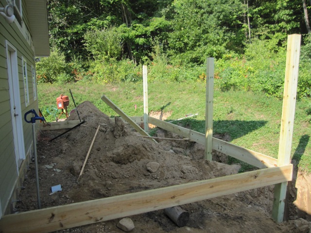
The first step was to dig holes for the four footings that will support the structure. The building inspector recommended that we design for additional weight due to the likelihood of snow drifting on the shallow roof, so the footings need to be pretty big. We rented a small backhoe to make the digging easier.

After a few hours Dan had all four holes dug to a depth of 42 inches as required.

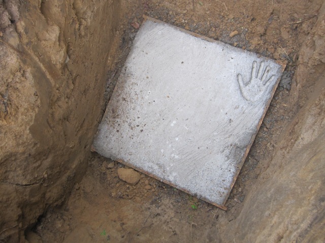
Into each footing hole goes a plywood form that’s about 29 inches square and 6 inches high. Strictly speaking we could meet code requirements with footings a few inches smaller, but making them a little bigger than required takes minimal extra time and concrete, and it will give us a little more leeway when positioning the posts.

September 4, 2012
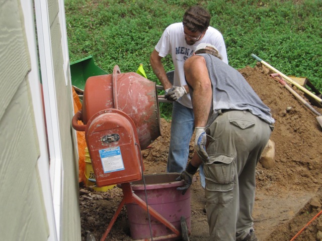
Jay and Dan mixed and poured the concrete for the footings.We used a basic bagged concrete mix, nothing special, and it took a total of 26 sixty-pound bags for the four footings.

By the next morning the concrete was set up well.

September 6, 2012
Dan drilled 1/2″ holes into the concrete stem wall of the shop, and attached a ledger with concrete anchors. Before attaching the ledger he liberally caulked behind it at the top, to prevent moisture and insects from migrating into the structure of the wall. All of the wood at or below floor level is pressure-treated.

We stood up the posts on their footings, and temporarily attached a few floor joists and the beam in front using small screws, strong enough to hold the boards in place but allowing easy repositioning. We nudged the posts back and forth to get them plumb and to get the whole frame level and square.

September 7, 2012
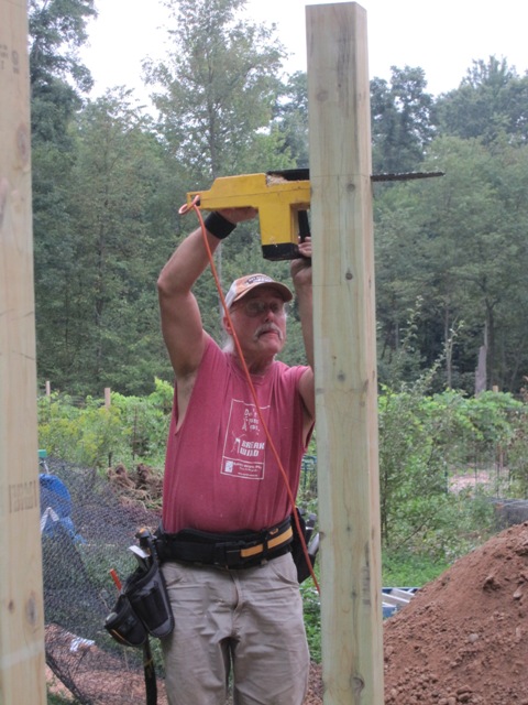
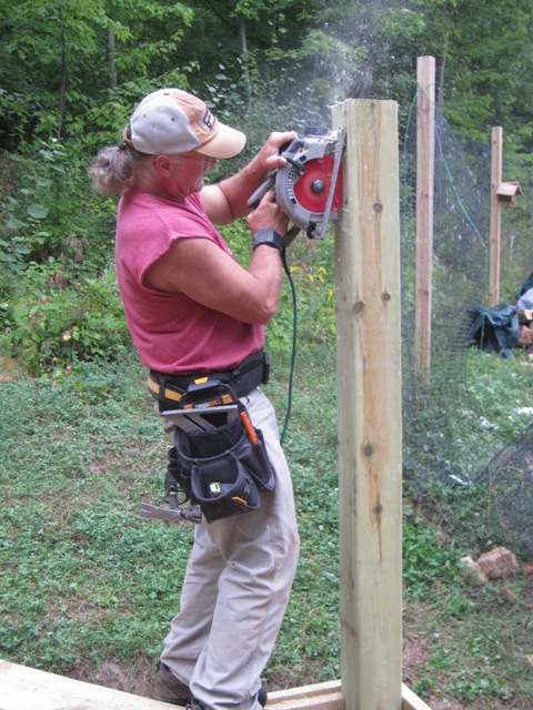
After carefully marking out the cut lines, Dan cut the posts to length and notched them to receive the upper beam that will support the roof.

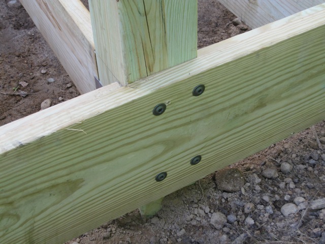
We set the upper beam, which is made from two 2×12’s, and tacked it up with small screws. Once it was all in place, we went back and readjusted the posts to get everything as level and square as possible. Then we anchored the beams solidly to the posts using heavy “power lag” construction screws that are rated for outdoor use on treated wood. The upper beam sits in notches in the posts so the screws just keep it in place and don’t support any weight, but the lower beam is directly supported by the lag screws shown in the second photo below. These screws will carry half the floor load so we used four 3/8″ lags in each post, which will put a maximum shear load of about 500 pounds on each screw and they should be plenty strong.

With the posts and beams solidly anchored together, we started backfilling the footing holes and tamping the sand down around the posts as we filled them. We filled the first one before removing the outside floor joist so the tractor could reach the next, and Dan kept checking the posts with a level to make sure we were keeping them plumb.

Once all the holes were filled, Jay graded the area so that water can drain away from the back of the house on the north side, under the shed on the east side, and down into the garden to the south. We don’t often get rain heavy enough to have surface water moving like this, but occasionally we get a downpour strong enough to create a small “river” so we want to make sure it’s directed away from the structure and won’t pool anywhere.

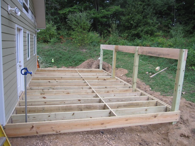
Once the filling and grading was done, Dan cut and fit the floor joists. They went up pretty fast, and it’s starting to look like a floor now. The blocking near the center of the joists keeps them from twisting, and it will also support one seam of the plywood floor. We’ll put in lighter-weight blocking where the other two seams will be, so the plywood will be supported on all edges. As you can see in the photos below, the outer frame members sit 3/4″ higher than the floor joists so the edges of the plywood will be covered on all sides.

September 11, 2012
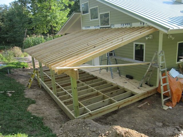
To support the roof Dan attached a ledger to the side of the house, anchoring it into the wall studs with heavy construction lag screws. Then he started cutting and fitting the rafters. The window above limits how high we can put the roof, and in order to maintain at least a 3/12 pitch the rafters get a bit low on the east side (to the right in these photos). In order to maximize the headroom we used 2×6 rafters spaced 12″ on center, which takes more rafters than if we’d used 2×8’s but it gives us 2 inches more headroom.

By the end of the day Dan had laid all the rafters in place and the roof had taken shape. Next we need to get them all securely anchored down and have the framing inspected before we can apply the floor and roof sheathing.

September 12, 2012
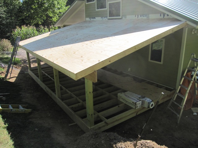
Dan attached the fascia to the front of the rafters, while Jay installed “hurricane straps” as required by code to anchor the roof to the wall.

Then we moved on to the roof. Dan nailed on the sheathing and it went up pretty fast.

September 13, 2012
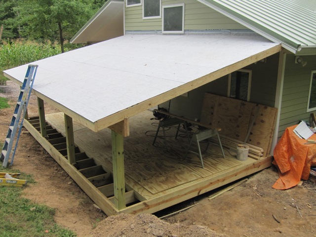
We used a peel-and-stick roof underlayment that’s meant for use under metal roofing. It has a white non-skid coating so that it’s relatively safe to walk on, and it sheds water so it will work as a waterproof roof temporarily until the metal roofing is installed.

Dan started working on the floor, screwing down the treated 3/4″ plywood to the floor joists and blocking.

Around the bottom Dan attached some of the fencing material that we had left over from the deer fence, to prevent animals from crawling under the floor. The bottom edge is buried under the dirt and flared outward so it will be relatively difficult for anything to dig under it.

October 1, 2012
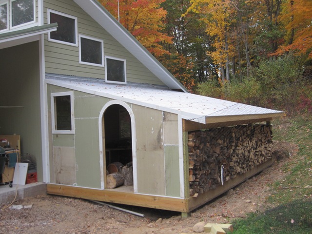
After Dan finished the floor and added the front wall and doorway, we stacked our firewood along the east side where it should get enough airflow to dry well. Once the wall was in place and covered with plywood sheathing, it was fairly dark inside so we decided to add a window to let more light in.

Dan framed in an opening to fit a window that we had salvaged from an old storm door, and boxed it in with fiber cement trim board to match the rest of the house. This makes it a lot lighter inside the shed.

October 2, 2012
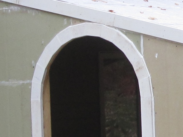
Dan finished up the trim and siding today. He pieced together some leftover pieces of fiber cement siding board so it looks a bit odd but once it is painted it should look seamless and match the rest of the house. He had to cut and fit 12 trapezoidal segments of 1×3″ fiber cement trim board to make the arch. We’re still waiting for the roofers to come install the metal roofing so the “roof” is still just the peel-and-stick underlayment but it’s rated for a few months of exposure and it should hold up until it’s covered with metal.

October 4, 2012
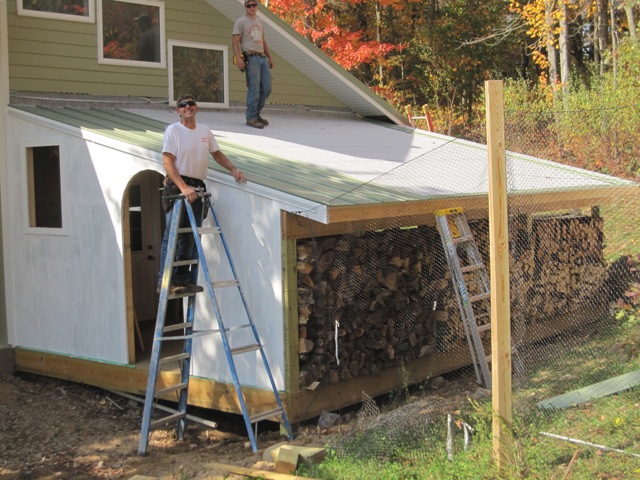
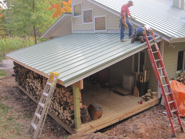
The roofers installed the metal roofing today. It went up pretty fast except for the corner where it meets the soffit of the shop roof, which required some cutting and fitting.

While the roofers were roofing, Jay primed and painted the front wall. It’s pretty much finished now except for some flashing on the fascia and beam, and replacing the last row of siding above the roof.

Vineyard Update 2012

August 11, 2012
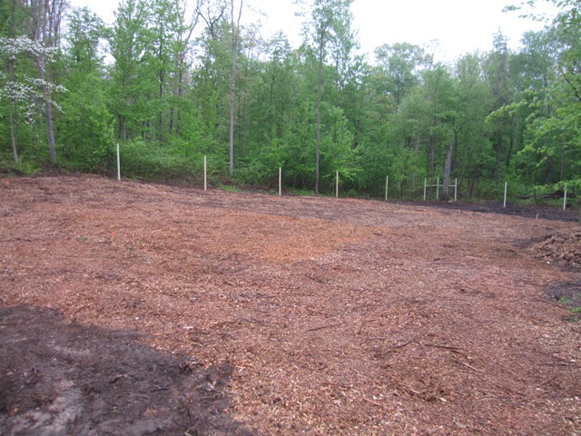
Last spring we prepared a vineyard site, put up a deer fence, and planted 40 grape vines along with some raspberries, blackberries, and asparagus. Since then the grapes have done well, although some of them were injured by late spring frosts this year. Here’s a pair of photos showing how it looked in the spring of last year just after we had cleared and mulched it, and how it looks now:

Here’s a closer view of the four rows of grape vines, with other berries and asparagus planted in the rows between. The second photo is taken from the southeast corner looking back toward the house.

Most of the vines did very well, and the photos below show Leon Millot and Frontenac vines with canes trained along the trellis wires.

Grapes are not expected to produce a crop until their third year, and it is generally recommended to prune off all the flower clusters to keep them from setting any fruit while they are still getting established. But we did let a few of the more vigorous vines set one cluster of grapes each, just enough for a taste and not enough to unduly stress the young vines. The first photo below shows a cluster of Marquette wine grapes, and the second shows seedless Reliance grapes that will turn pink as they ripen.

Next year we can expect a moderate crop of perhaps 5 pounds per vine for those that are doing well, but less for those that are slow to establish or were injured by the spring frosts this year and are still recovering. That should be enough for a couple of 5-gallon batches of wine next year, and several times as much once the vines are mature. In the mean time we are practicing our winemaking skills using grapes of the same varieties we’re growing (Leon Millot, Marquette, Frontenac, Frontenac gris) that we purchased from Taylor Ridge Vineyard, so that we’ll have some experience by the time our own grapes are ready.

Cooling System, Enhanced

July 15, 2012
We installed our original cooling system in July 2010 and it has worked reasonably well, but over the last few weeks we’ve had a hot spell with daytime temperatures mostly in the upper 90’s and well over 100 degrees Fahrenheit for a few days. That’s normal in some parts of the world but in Michigan, we consider that HOT! Over two weeks of unusually hot weather the house reached 77 degrees at the warmest point when it was 105 outside, which is actually pretty good since we’re cooling the entire house for about 30 cents per day, but 77 degrees inside is a bit warmer than we would like and we anticipate more hot weather to come. The original cooling system circulated water through the radiant floor slabs and through a copper coil heat exchanger in one half of the cistern, so we decided to add a second heat exchanger in the other half of the cistern in order to increase the capacity of the system, both in terms of power (BTU/hour) and total heat capacity (BTU).

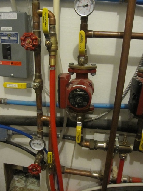
The first order of business was to improve the plumbing in the mechanical room. Previously I just connected the cistern loop with hoses connected to the drain and fill valves of the hydronic heating (now cooling) plumbing. This connection worked okay but it was only meant to be temporary and probably restricted the flow rate somewhat as the water had to flow through the drain/fill valves. So, I disassembled the copper piping and added two T fittings for direct connections to the cistern cooling loop. I also relocated one of the temperature gauges so that I can directly measure the temperature of the water returning from the floor slabs. This will permit a more accurate measurement of the system’s performance. The photos below show the plumbing before and after this change. The vertical red 5/8″ PEX tubing runs to the heat exchangers in the cistern. Water returns from the floor slabs through the manifold at the very bottom of the photo, then flows up through the temperature gauge and then out the lower T fitting and down to the cistern. It returns through the long red tube that’s visible in the photo, into the upper T fitting and then up and around to the circulator pumps and back out to the floors through the upper manifold. This is essentially the same as it was before except that it’s now a permanent connection, with the temperature gauge moved down to the warm side of the loop so I can directly measure the temperature drop across the heat exchangers. In the winter we’ll close the two valves to the cistern lines and open the one in the middle, so the heating water won’t flow through the cistern loop.

After the plumbing in the mechanical room was redone, I opened up the cistern to add a second heat exchanger. This was the first time we had opened it in about 2 years, so it afforded a good opportunity to examine the clarity of the water. Since we’ve had a hot, dry spell for the last 4 weeks we have been using a lot of cistern water for the gardens, and we’re down to about 36 inches or 4,300 gallons, out of a total capacity of 12,000 gallons. Hopefully we’ll get some significant rain soon to replenish our irrigation water supply, but we can refill it from the well if necessary.

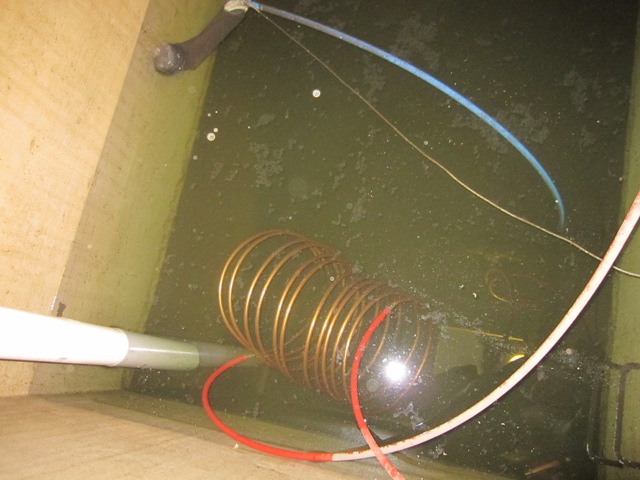
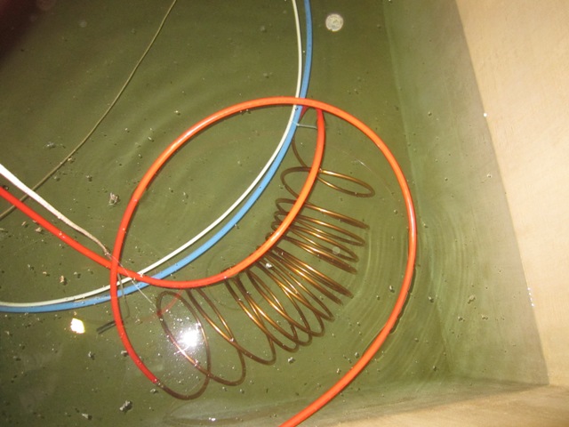
The first photo below shows the first (north) half of the cistern where the rainwater enters through the white pipe in the lower left of the photo. The copper coil is the heat exchanger that I installed 2 years ago for the original cooling system. The camera’s flash exaggerates the small amount of material floating on the surface, some of which fell down when I opened the hatch. You can see that the bottom is covered in dark sediment, which is not surprising since this side receives water from the roof. I didn’t climb down far enough to measure the sediment but it appears to be less than 1/8 inch thick. This will have to be cleaned out someday, but probably not for quite a few years. The second photo shows the new heat exchanger coil in the second (south) half of the cistern. It’s quite striking how much cleaner the water is on this side, because most of the sediment settles out on the first side before water flows by gravity through the floating filter (visible at the upper left of the first photo) and into the second side. We pump water out through another floating filter (not visible) in the second side where the water is cleanest. There is a 5-micron filter attached to the cistern pump in the mechanical room, and after nearly 3 years of operation we still haven’t needed to change the filter cartridge because there is almost no sediment in the water coming from the second half of the cistern.

The two heat exchanger coils are connected in parallel through T fittings as shown in the photo below, so that the water splits and flows through both of them together rather than flowing first through one and then the other. This will transfer approximately the same amount of heat into both halves of the cistern, and more importantly it should offer considerably less flow resistance than if they were connected in series so we should get a higher flow rate using the same amount of energy to run the pumps as before.

In the first post on our cooling system about 2 years ago, I reported that the system had a flow rate of 1.8 gallons per minute on the low-speed pump setting, and had a 5 degree temperature drop through the single heat exchanger in the cistern. That gave us an Energy Efficiency Rating (EER) of34, which is about 3 times as efficient as a good air conditioning system. After improving the plumbing in the mechanical room and adding the second heat exchanger, I measured a flow rate of 2.6 gallons per minute on the same low-speed pump setting and a 6-degree temperature drop. This increases our efficiency by 73% for an EER of about 60, which is 5 times as efficient as a good air conditioner. Using only 120 watts of electricity to run the pumps, the system is removing about 2300 watts of heat energy from the house. It can’t sustain this rate indefinitely because the cistern water will warm up until it reaches equilibrium with the rate of heat transfer into the earth through the cistern floor and walls, so I expect the efficiency to drop a little over the next week or two. But it’s still many times more efficient than the best available air conditioning systems and heat pumps. Its total cooling capacity is very small however, so it is practical only because our total cooling load is very small due to the extreme level of insulation in the house, because our south-facing windows have carefully designed overhangs that block direct sun in mid summer, and because we use very efficient appliances that add very little additional heat to the house.

Deck Ramp

April 29, 2012
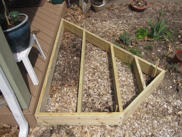
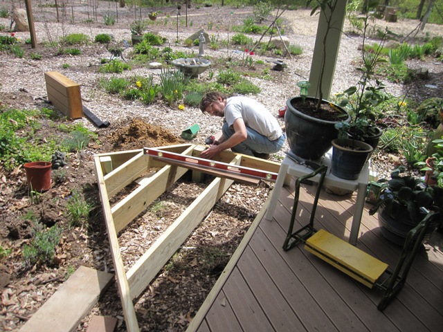
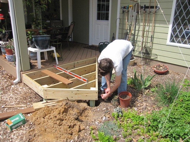
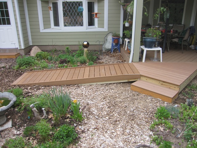
When we built the deck 2 years ago we had planned to add a ramp to make it more accessible, and we’re finally getting around to building it. The ramp will attach to a landing that extends off the east side of the deck so the first step was to build the landing. It’s a simple structure that will be attached to the deck and supported by two posts. After marking the post locations Jay dug the post holes.

Once the posts were in place, Jay leveled the ramp and screwed it to the deck and posts with heavy-duty anchor screws that are rated for outdoor use with treated lumber.

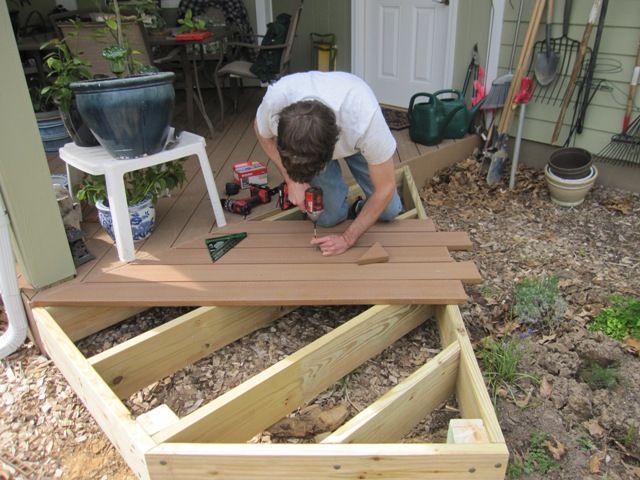
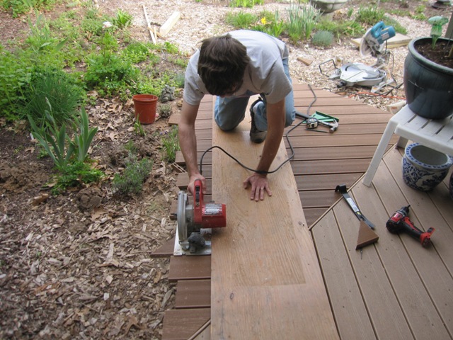
After the landing was secured in place, Jay attached the decking and then trimmed the ends flush.

The photos below show the finished landing and the step, which just sits on the ground in front of the landing. The ramp will attach to the front face.

May 6, 2012
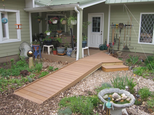
The ramp is made of treated 2×6’s and is ten feet long by three feet wide. Rather than cutting the 2×6’s at the far end, Jay just dug a trench for them so that the end of the ramp will be at ground level.

Here’s the finished ramp with the decking attached. The side rails are made of solid 1×6 composite decking and they extend above the deck surface to prevent wheels from rolling off the sides of the ramp. This works well for a wheelchair and garden carts too.

The Tank Springs a Leak

Includes affiliate links that help offset our expenses at no cost to you. Affiliate programs and affiliations include Amazon Associates and the eBay Partner Network.

The disturbing sight of water seeping out from under these baseboards could mean only one thing: a leak from the 2500-gallon heat storage tank that’s on the other side of the wall. The water level gauge indicated that it had dropped about 10 inches meaning that we lost about 300 gallons before noticing the leak, and since there was only a trace of water on the floor the 300 gallons had to seep down into the ground under the concrete floor (which should be relatively harmless) and also up into the cellulose insulation that surrounds the tank (which is very bad).
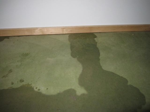
When constructing the tank we anticipated that it might develop a leak around the plumbing fitting at the bottom, which provides a way to drain the tank, so we left this fitting accessible through a hole in the wall of the mechanical room. As you can see below there is water underneath the fittings, but the underside of the fittings seems dry which suggests that the tank may have cracked somewhere else. We connected a hose to the drain line in order to carry the water out beyond the driveway, and then opened the big valve to drain the tank. That doesn’t fix the problem of course, but at least it keeps any more water from entering the house so we have time to devise a solution.

September 3, 2011
If the polyethylene tank is indeed cracked, it should be possible to repair it with a plastic welder. But first we have to solve the more difficult problem of removing the soggy insulation around the bottom of the tank. It’s possible to climb inside the tank through the top hatch which is accessible from the mechanical room, but the cellulose insulation around the bottom of the tank is thoroughly soaked and needs to be removed. In addition, we may not be able to locate the leak without removing all the insulation. The 8-foot diameter by 7-foot high tank is surrounded on all sides by 12-16″ of cellulose insulation packed between the tank and the walls that contain it, and there’s about 4 feet of insulation on top of it which means we need to move a total of over 20 cubic yards of insulation! For comparison, that’s about the capacity of this Peterbilt 357 dump truck:

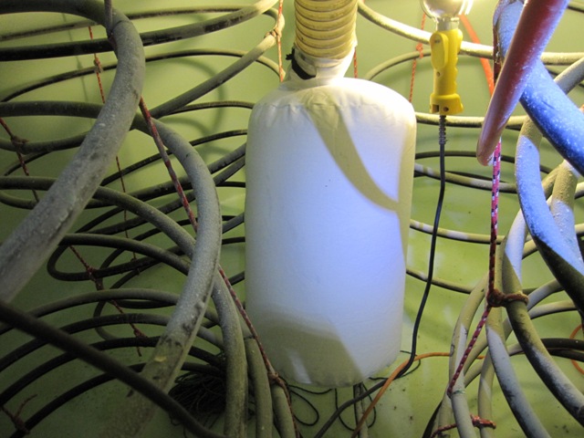
Moving all this material is going to be a big, messy job! After pondering the problem for a while, we’ve come up with a way that we think will enable us to move all the insulation from around the tank into the attic above the garage, and then to move it back around the tank when the repair is done. What we want is a “vacuum” with a hose that will suck up the insulation from around the tank and blow it out through another hose. Shop-vac type vacuums won’t work because they will only collect material into a sealed cannister and even a large 20-gallon shop vac would have to be emptied 200 times to move this much material. And a typical cellulose insulation blower won’t work because it’s designed to have insulation bales dumped into it from the top and doesn’t provide a vacuum-type suction hose. What we’re going to try is a small single-stage dust collector that we bought from Harbor Freight:

This unit is designed to suck in wood chips and sawdust and to blow them into a large filter bag. By connecting an outlet hose instead of the filter bag, it should be able to suck up the insulation material from around and over the tank and blow it into the attic, and then to reverse the process after we fix the tank. The photos below show the protective screens within the inlet and outlet openings, and these will have to be removed because the cellulose would easily clog the inlet screen. This also creates a safety hazard so we’ll make sure the inlet and outlet hoses are very securely attached, and we’ll also keep a shut-off switch close by in case the unit sucks in anything that causes a jamb. Try this at your own risk!

Removing the screens was easy, and revealed a pleasant surprise. We thought a low-end dust collector like this would have a plastic impeller but it is actually steel. The steel impeller should be able to take the abuse we’re about to give it. Tomorrow we will put it to the test.

September 4, 2011
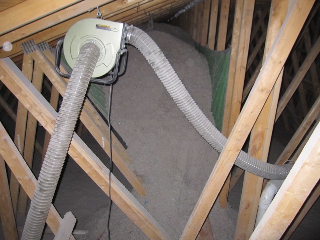
The first photo below shows the top of the tank area, covered in several feet of insulation. In order to store the 20+ cubic yards of material, I secured tarps into the bays of the roof trusses to create giant storage bins. The dust collector is hung from a truss so that it will blow insulation into the bin through a 10-foot outlet hose, after drawing it up through a 20-foot inlet hose.

Here’s how things looked after about an hour of blowing. The dust collector is working extremely well! The top of the tank is now visible after removing the first several feet of insulation, and the bin is filling up fast. The volume of insulation around the tank is about 20 cubic yards but it’s packed densely so it is expanding quite a bit in volume as passes through the blower, and will be more like 30 cubic yards once it’s all removed.

September 5, 2011
The blower continues to perform very well and has removed almost all of the insulation. There was no noticeable dampness until the last 6 inches or so on the bottom. At that point I redirected the blower’s outlet hose to blow the slightly-damp insulation out into the attic, where it will dry out and will just add a little insulation over the living room. That way we’ll only be putting dry material back around the tank after repairs are done.

It took a total of about 4 hours with the blower to remove all the insulation, plus a couple of hours to set up the equipment and tarps. Here are photos showing the two truss bays filled with about 30 yards of insulation that was removed. Once repairs are complete we’ll blow all this back around the tank.

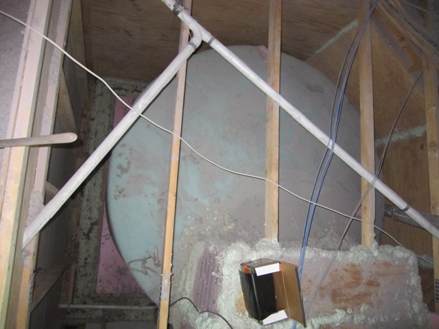
The last 2 inches or so on the bottom was pretty wet and the blower wouldn’t lift it, so I scooped it into trash bags and hauled them up on a rope. In all it’s only a small about of material that we’ll have to discard. Here’s how the tank looks now that it’s fully exposed. There is no apparent damage from the water and it’s all exposed to dry out.
September 10, 2011
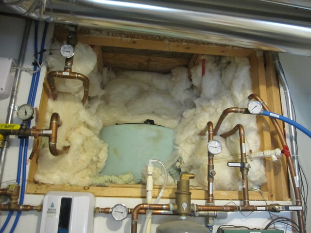
The next task was to remove the fiberglass insulation packed around the tank hatch and plumbing. We used fiberglass in this area instead of cellulose in order to make it easier to access this area if needed. Next I’ll cut an opening in the plywood above the hatch so it can be accessed from the attic above.
September 12, 2011
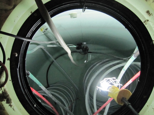
Once the hatch was open, I used a small submersible pump to remove the remaining few inches of water. These views are looking down into the tank from the attic.
September 17, 2011
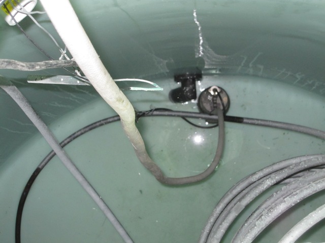
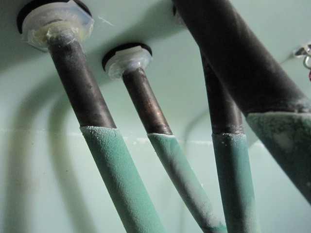
Here are some images taken down inside the tank. The copper heat exchanger pipes are covered with dark cupric oxide, which is formed when the copper reacts with oxygen in the water and it actually protects the copper from further corrosion. There are also some white mineral deposits from calcium in the water.

The mineral deposits were especially noticeable near the top of the water level, where they have grown fairly thick and are tinged with blue from copper dissolved in the water. The water tends to be the hottest at the top of the tank, causing the formation of more calcium scale.
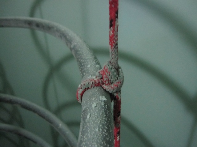
Some problems were immediately evident. After 2 seasons of use, the nylon cable ties used to secure the tubing to the support ropes had become brittle, and about half of them had broken. These were put in place during the tank construction in order to prevent the pipes from rubbing against the ropes causing abrasion of the copper. The pipes are supported using knots every 3rd coil or so, and the knots are still in good shape. The polypropylene rope shows no signs of degradation.
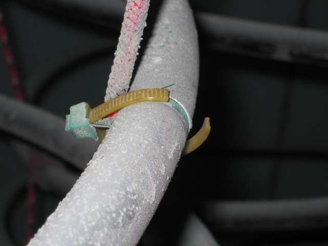
The first photo below shows where one of the coils has shifted, placing it in direct contact with one of the vertical copper tubes leading to the bottom of a coil. Over time this could lead to failure of the tubing at this point, due to abrasion where the tubes touch each other and rub together when the coils move slightly due to changes in fluid flowing through them. This will be easy to fix, by bending the vertical tube out of the way. The second photo below shows one of the PEX tubes that holds a temperature sensor. Originally it was held away from the copper by a nylon cable tie, which has broken allowing the PEX to rub against the copper. This could also lead to failure over time and it will be simple to fix it now.

THE CRACK
Here at last is what caused all the trouble, or at least we hope this is the only cause! The crack is only about an inch long, and is on the side wall about 8 inches up from the bottom of the tank. It was difficult to photograph well but it’s definitely a crack that extends all the way through the wall. The first photo shows it illuminated from inside the tank and the second photo, also taken inside the tank, is with light shining through from the outside. There is evidence of an impact at this location, as if something hit the wall during manufacturing or transport and caused it to crack, and it is brown-colored as if water has seeped through and left some deposits behind. Apparently it has been there since we installed the tank, gradually increasing in size until it had finally cracked all the way through the wall and let water seep through. Overall the tank does not seem to have gotten brittle from the sustained high temperature (140 degrees F), so this appears to be an isolated problem.
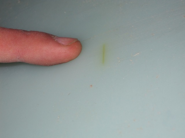
THE REPAIR
Repairing the crack was very simple, compared to all the work of draining the tank and removing the insulation around it. FIrst I drilled small holes at each end of the crack to keep it from propagating any further. Then I ground out a V-shaped channel about halfway through the tank wall, on both the inside and the outside of the tank.

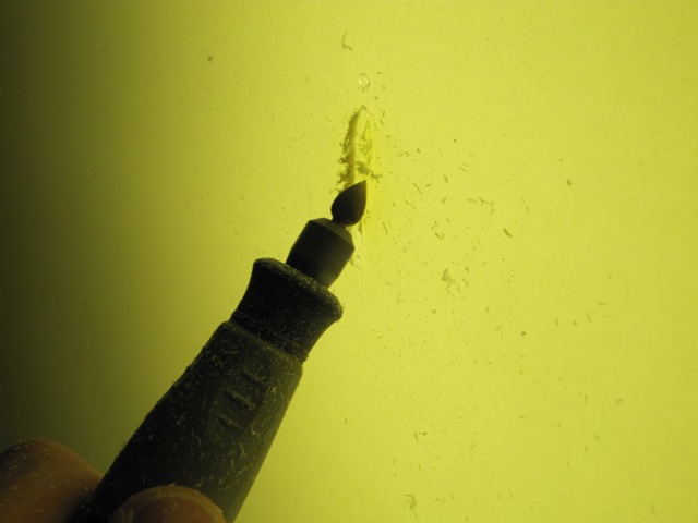
To repair the tank wall I used a Urethane Supply Co. Mini-Weld Model 6 Airless Plastic Welder, Model# 5600HT. It is like a large soldering iron but has a special tip through which a 1/8″ plastic rod is inserted. It comes with a variety of different kinds of plastic rods, and has a temperature control for welding various kinds of plastic including polyethylene which is the material of this tank. The welder melts the plastic rod together with the tank wall, filling the V channel and fusing it all together. It makes a bit of smoke and fumes as it melts the plastic so I used the outlet hose of the insulation blower, together with the filter bag that came with it, to provide a very effective fresh air supply inside the tank. I also wore a respirator with activated carbon filter cartridges so I wouldn’t be breathing any plastic fumes. It wasn’t practical to photograph the welder actually making the weld because it takes two hands (one to hold it and one to feed in the plastic rod), but the second photo shows it starting to heat and soften the tank wall around the V-channel. As soon as it was softened a bit I fed in the plastic rod and started filling in the V-channel I had ground out, and then went back over it all to melt the new plastic together with the tank wall.
I welded the crack both inside the tank and outside. The resulting weld looks ugly because it contains little bits of dark burned plastic that were left on the welder tip from when I tested it earlier. But it is nice and solid, having filled in the V-channel nicely and having fused it all together. It appears very unlikely to leak or crack again in this location.

October 4, 2011
After refilling the repaired tank with 55-degree water from the well, we began warming it up with the solar heat collection system It took about 2 weeks to reach 100 degrees F, and then it leaked again! Fortunately we hadn’t replaced any of the insulation yet, since we were waiting to make sure the repair would hold. Obviously it didn’t, and the photos below show that it’s leaking right through the middle of the crack in two places.

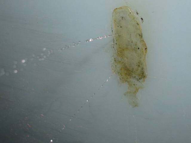
It’s not entirely clear why the repair failed, but a likely cause is that the plastic welding rod that came with the repair kit is made of low-density polyethylene whereas the tank is high-density polyethylene. The difference in chemical composition of the plastics may have prevented them from making a good bond, or it may have made them expand at different rates as the tank warmed up. It’s also possible that the V grooves I carved into the tank just weren’t deep enough, causing stress around the old crack to propagate into the repair material. In order to make a new repair with the same material as the tank, I harvested some plastic from the raised numbers molded onto the side of the tank to indicate the fluid volume. We can’t see them anyway once the tank is insulated, and this should make a better repair.

After grinding out the faulty repair, and creating deeper V grooves on the inside and outside, I melted these numbers back into the crack. I also applied heat to the area longer, to make sure that the repair material was fully melted into and blended with the tank wall. Sorry, no photos of that but visually it looks about the same as it did before.

October 15, 2011
Before refilling the tank, I installed a leak detector to give us an early warning in case it ever leaks again.I ran some speaker wire around the outside of the tank and scraped the insulation off at several points, placing it under the edge of the foam insulation that the tank sits on. I ran the wire out into the utility room, where I connected it to a Reliance Controls THP205 Sump Pump Alarm and Flood Alert. The alarm is quite loud and it should sound the moment any water reaches the wire.

Before replacing the cellulose insulation around the tank, I placed a 6-inch layer of foam packing peanuts around the perimeter of the tank and covered it with some landscape fabric. That way the cellulose should remain at least 6 inches above the bottom of the tank so if we do have a leak this should keep the bulk of the cellulose insulation away from the water. If the foam peanuts ever get wet they won’t degrade and they have enough air spaces to dry out eventually. I also boxed in the area around the repair with some scraps of foam board and filled the box with foam peanuts so that if it leaks in the same area again, I can get to it by cutting a small opening in the adjacent wall. Hopefully it will never leak again but just in case, this should make it possible to repair without removing all that cellulose again!

January 6, 2012
After refilling the tank again and waiting a few weeks with no leakage, I replaced all the cellulose insulation using the insulation blower. It wasn’t practical to take photos during the process but it was pretty much the reverse of removing the material. It went reasonably fast and took about 4 hours. It has now been about 10 weeks since we refilled the tank. The water alarm has remained silent and the repair has held, and we are once again heating the house with stored solar heat.

Vineyard Preparation

The land we cleared to the southeast of the house is a gentle south-facing slope that should work well for growing grapes and other fruit crops. Our vineyard will consist of four rows each 77 feet long with grape vines spaced 7 feet apart, giving enough space for a total of 44 vines. Grape rows are typically spaced about 8 feet apart but we spaced ours 18 feet apart to leave enough room for rows of fruiting shrubs in between. Rather than the monoculture that is typical of most vineyards, ours will be a diverse polyculture of grapes, raspberries, blackberries, currants, bush cherries, aronia, honeyberries, blueberries, asparagus etc. We’ll also grow perennial flowers among the fruiting shrubs in order to attract beneficial insect populations.

May 21, 2011
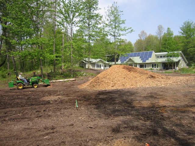
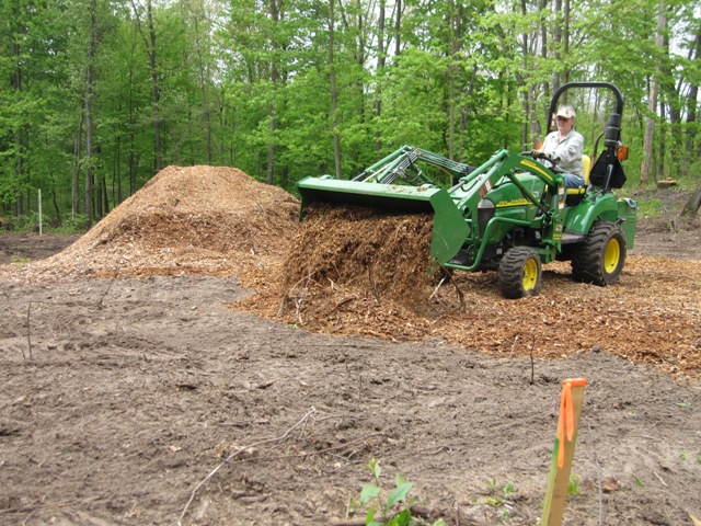
After clearing the brush and trees from the area to the southeast of the house, we began turning the area into a garden. The first step was to spread out the huge pile of wood chips that came from all the brush we cleared.

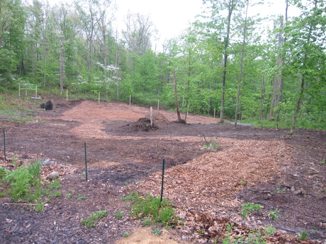
After a long day of spreading wood chips, we managed to cover the whole vineyard area and a path up through the new garden area to the south of the house. The first photo below was taken standing about 50 feet south of the house, looking southeast down toward the vineyard area. The second photo shows the whole vineyard-to-be, with the deer fence posts in the background.

May 22, 2011
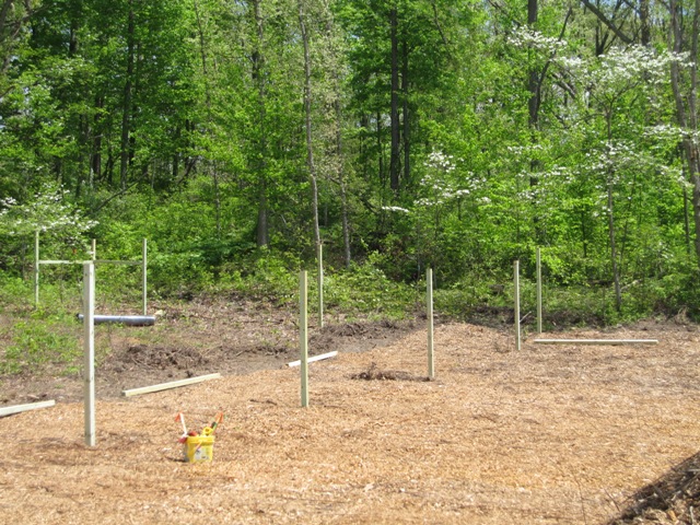
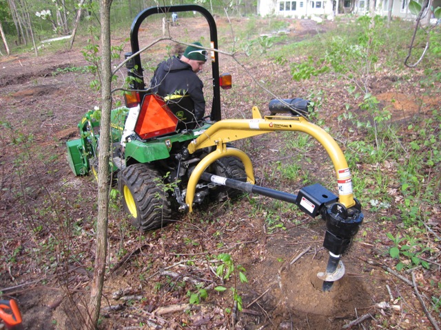
Today we set the posts for the trellises that will support the grape vines. We set 24 posts in all, and the auger on the back of the tractor helped a lot. Each post is 10 feet long and set 3 feet in the ground so they’re 7 feet high. The top support wire of the trellis will be 6 feet off the ground, and we may run another wire up at the top of the posts to help hold up bird netting if the birds start harvesting our grapes for us!
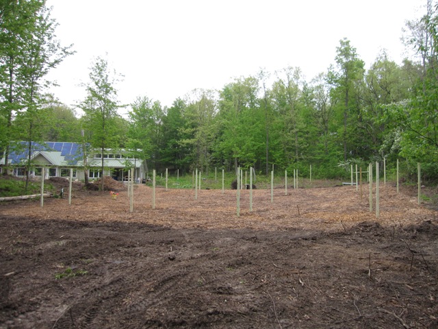
The first photo below shows the view from the south of the vineyard, looking northward up the hill. The second photo shows the view from the northwest corner looking southeast back down the hill. Each trellis row runs north-south and consists of 6 posts. The pair of posts at the end of each row are only 7 feet apart so that we can place a diagonal brace between them to support the tension of the trellis wires. The other posts are 21 feet apart and will have 3 vines between each pair of posts.

Grapes

Since we have room for about 40 vines, we decided to plant 8 vines each of 4 different varieties for wine, and 2 vines each of 4 different varieties of seedless table grapes. After researching what grapes would do well in our climate we settled on the following varieties:

  8 Leon Millot, a cold-hardy French hybrid wine grape   2 Canadice, a red seedless table grape
  8 Frontenac, a dark blue wine grape released by the University of Minnesota in 1996   2 Mars, a blue seedless table grape
  8 Frontenac Gris, a gray-colored sport of Frontenac for white wine   2 Himrod, a white seedless table grape, good for making raisins
  8 Marquette, a more recent (2006) introduction from the university of Minnesota   2 Reliance, a red seedless table grape

June 1, 2011
Once the vineyard preparation was done, we planted the 40 grape vines that we ordered from Miller Nurseries (now Stark Bro’s) and Burpee Gardens. The photos below show how they looked shortly after planting. We pruned them back to have just 2 or 3 buds each and we’ll select the strongest shoots to train up as the main trunk of each vine. The whole area is now mulched in wood chips to help conserve moisture, and so far they haven’t needed any supplementary water.

Deer Fence

All the plantings in our new garden space will be for naught without some protection from deer, rabbits, woodchucks, raccoons and the like. We’re building a deer fence around the perimeter that should exclude all of these pests, perhaps not 100% of the time but enough to limit our losses. Deer can jump a 12 foot fence if they are sufficiently motivated, but a fence that tall would be very costly and a fence only 7 feet high is usually sufficient if it is difficult for the deer to judge the fence’s height visually. If jumping does become a problem, rather than extending the fence upward it will be more effective to extend it outward at the top. In addition to the fencing, which is essentially sturdy plastic-coated chicken wire, we’ll run electric wires around the outside to discourage climbing raccoons.

May 16, 2011
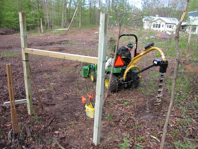
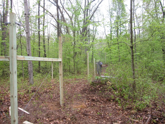
Our nephew Nash used the power augur on our tractor to drill all of the post holes, and set the posts around the perimeter. In the first photo below you can see a corner brace, which will have a diagonal wire tensioned to resist the pull of the fence on it. This is at the far northeast corner of the fenced area, looking west toward the house.

This is the fence along the south edge, and you can see the tensioned corner brace in the photo below. If you look closely you can also see the black wire that runs 7 feet off the ground on the outside of the posts to support the fencing at the top.

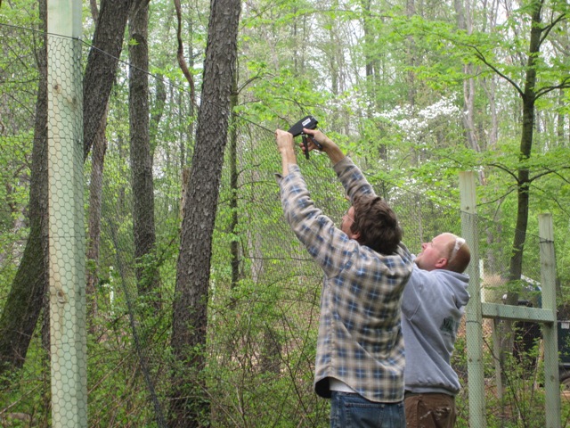
This fencing material is not placed under high tension as livestock fencing usually is. It’s fastened to the top wire with metal hog rings that crimp around the fence and the wire, and then the fence is stapled to the posts. It flares out about 6 inches at the bottom, and this flap will be anchored to the ground to discourage animals from digging underneath. A determined woodchuck or rabbit will still be able to get under it, but it should discourage them for the most part once all the sections of fence are in place.

Appliance Garages

March 4, 2011
The first photo below shows the cottage kitchen wall way back when it was first painted, where you can see the deep boxes that we set into the exterior wall to the right and left of where the cooktop will go. These boxes are about 12 inches deep, and the second photo shows how they look now that they are finished, as the tambour doors slide up to provide storage for small appliances.

It would have been convenient to put electrical outlets inside the garages so that we could leave appliances plugged in and just slide them back for storage. But this could pose a fire hazard if an appliance were to be accidentally left turned on while inside the garage. Therefore we decided to put electrical outlets only outside the garages, right above the doors as shown below. This is a bit less convenient but it ensures that we can’t put an appliance away while it’s still plugged in.

Here’s how the main kitchen looked right after the drywall was painted. Whereas the cottage kitchen’s appliance garages were set into an exterior wall that was 16″ thick, the main kitchen’s walls adjoin other rooms in the main house so we simply left holes in the wall as shown below.

Here’s a view of the finished west wall of the main kitchen, with the appliance garage door open and closed. It’s 30 inches wide and 16 inches deep so it’s big enough to hold several small appliances, and with the door closed it makes things a lot less cluttered.

On the north wall of the kitchen is the cooktop with an appliance garage on either side. These are only 12 inches deep but still large enough to store quite a bit.

The cottage kitchen’s 12-inch-deep appliance garages were set into an exterior wall that is 16 inches thick so they are hidden, but the main kitchen’s wall adjoins other rooms so the plywood enclosures protrude through the wall into those rooms. These will be surrounded by cabinets so they won’t be visible once the cabinets are in place. Until then, they make rather quirky shelves. At least they’re better than open holes in the walls, especially in the bathroom!