How I Made a 4th Axis Harmonic Drive

Includes affiliate links that help offset our expenses at no cost to you. Affiliate programs and affiliations include Amazon Associates and the eBay Partner Network.

After finishing my Modular CNC Controller I built this 4th axis attachment for my CNC router and my milling machine. This will let me machine parts such as gears, and carve 3D patterns wrapped around cylindrical shapes. In the Part 1 video I build the main drivetrain components, using a harmonic drive gearbox to get precise angular positioning and high torque with low backlash.

In the Part 2 video I weld and machine the steel enclosure, install the harmonic drive system, and try it out.

In this video I apply Powder Coating to the housing.

Documentation

The Harmonic Drive web site has detailed information about the style of gearbox that I used. The Catalog link on that page provides detailed documentation about this family of ultra-low-backlash gearboxes.

I bought the 3-jaw front-mounting self centering lathe chuck from Shars. Any similar chuck should work, provided that it can be mounted from the front.

I bought my stepper motor on Ebay after quite a bit of searching to find one with the specs I wanted, including the 8mm output shaft to fit the coupling on my particular gearbox. Here is a link to a similar Nema 23 stepper motor on Amazon.com, but with the more common 1/4″ output shaft.

Aquaponics

Includes affiliate links that help offset our expenses at no cost to you. Affiliate programs and affiliations include Amazon Associates and the eBay Partner Network.

Aquaponics is a combination of aquaculture (raising fish) and hydroponics (growing plants without soil). The wastes from the fish are broken down by bacteria living in the growing medium, and converted into a form that can be used by the plants.

Integrated Vertical Tube System
Here’s a drawing and a photo of the integrated vertical tube aquaponics system we built. The photo shows the tubes in the planting/harvesting position; normally they are rotated 180 degrees so that the openings face the window.

I made the drawing using SketchUp, a great free 3-D drawing program. If you have SketchUp and want my drawing file you can download it by clicking here.

To make the grow tubes, I cut slots across with a hack saw and then heated the plastic with a heat gun to soften it. Once it was soft I pushed in a tapered wooden plug to hold it open until the plastic hardened again. I did this outside because the PVC gives off some fumes when you heat it. The second photo below shows a close up of one of the openings after the tube was filled with pea gravel.

The PVC caps on the bottom of the tubes have slots cut around the edges with a table saw, so that any water that might drip out around the plants can just run down the outside of the tube and through the slots. Otherwise the cap would seal against the funnel and the water could not drain. Normally the water flows down through the tube and out the holes I drilled in the bottom of the cap.

The photo below shows the top of the system, with the flow control valves that regulate the flow of water to each tube. These were necessary in order to balance the flow because without them, most of the water runs into the tube closest to the pump. Note that the tubing is black in order to prevent algae from growing inside it, but after a while it will still develop a film inside from beneficial bacteria that break down the fish wastes. We found that it was necessary to clear the tubes out now and then, by closing all but one valve and turning the pump off and on. The sudden surge of water when the pump starts is enough to clean the accumulated biofilm that adheres to the inside of the tubing.

April 3, 2007  We got fish today! They are about 3″ long and cost us $3 apiece. Their first meal was a small handful of earthworms, which they ate eagerly. I think the one in the bottom picture is burping.

Here’s my new experimental setup to permit multiple fish to each establish a breeding territory in one tank:

5-2-2007  Here’s our first harvest of lettuce, which totaled a whopping 9 grams (0.3 ounces)! The lettuce is a red variety so the color is normal for this type.

6-3-2007: We’ve had quite a few salads now and the plants are doing great. The spinach is spindly but the basil, upland cress and lettuce are thriving.

8-14-2007 We’ve got babies! We hadn’t looked closely for a while so we were surprised to see about 50 little tilapia in the tank today and they’re already over 1 cm long. The water isn’t normally this cloudy but we just cleaned the tank so it’s all stirred up.

The adults are doing well too, and they’ve grown quite a bit.

9-3-2007: The first group of babies have grown to about 1″ long, and we now have a second brood of little ones. The adults pretty much ignore them but the larger babies will “thin out” the smaller ones for us. It’s survival of the fittest in this tank!

Epilog: We shut down this project in the spring of 2008, in preparation for moving to Michigan. We ate the largest of the fish, which weighed in at about 10 ounces – not quite market size but enough for a taste anyway, and it was pretty tasty.In retrospect we wouldn’t undertake any serious fish-raising project without first developing a food source, as purchasing fish food getsrather pricey plus there’s no control over its contents. We’d also use a tank that’s easier to clean!

4th Axis Engraving a Micrometer Dial

This project is the first real test of the new Modular CNC Controller and 4th Axis Assembly that I built. I used themto engrave a micrometer dial to make an adjustable carriage stop for my metal lathe, which is based on a YouTube video by Tubalcain. Here’s how the finished part looks:

The first video shows how I modeled the part and created engraving toolpaths using AutoDesk Fusion 360:

The second video shows the machining of the dial using the toolpaths generated in Part 1:

I ran into some difficulties during the machining, one of which was that my cheap stepper motor drivers were not able to keep up with the pulse rate coming from the DDCSV1.1 control panel. Upgrading them to higher-end drivers solved the problem, and the specific ones I’m using are the KL-5056 from Automation Technology:

This driver supports a power supply up to 50V and can deliver up to 5.6A of current, which is more than I need for the steppers I’m using at the moment, but I also plan to use these drivers someday to run my milling machine where I’ll need bigger stepper motors. I have the drivers set at 2.7A for the smaller stepper motors that I’m using on the CNC Shark router and the 4th axis. I noticed that in addition to solving the problem I was having with lost steps on the Z axis, the improved drivers also gave noticably smoother motion and less noise.

Modular CNC Controller

Includes affiliate links that help offset our expenses at no cost to you. Affiliate programs and affiliations include Amazon Associates and the eBay Partner Network.

I built this modular CNC controller to run a variety of different machines in my shop. My first application is to replace the old controller on my CNC Shark router but I wanted the flexibility to reuse the same hardware on different machines, so I came up with a standard connector layout that will let me swap the controller and power supply for different needs. Initially I’m using the DDCSV1.1 Control Panel but I could someday replace it with a different standalone controller or an Ethernet SmoothStepper and Mach3 or Mach4 software.

The second video covers details of wiring and configuration of the CNC controller.

DDCSV1.1 Control Panel Documentation

Here is the DDCSV1.1 User Manual that contains a wealth of information about this panel, including details of wiring and operation.

Construction Details

Here are links to most of the parts that I bought on Amazon.com:

  1. DDCS 4 Axis Control System
  2. KL-5056 20-50VDC 5.6A Digital Bipolar Stepper Motor Driver – 32 bit DSP Based
  3. BUD Industries AC-405 Aluminum Chassis, 7″ Length x 7″ Width x 2″ Height, Natural Finish
  4. 2P5T 2 Poles 5 Position Rotary Switch
  5. Ferrule Crimp Tool Kit
  6. Remington Industries 18UL1007STRKIT UL1007 18 AWG Gauge Stranded Hook-Up Wire Kit
  7. Connectors Pro DB37 Female D-Sub Solder Type Connector, 10-PK
  8. D-Sub Hex Head Screw with Nut 4-40UNC
  9. 400W 36V Switch Power supply, DC power S-400-36 11A
  10. URBEST Inlet Module Plug 5A Fuse Switch Male Power Socket 10A 250V 3 Pin IEC320 C14
  11. US 3 Pins Power Socket Plug Black AC 125V 15A
  12. Blue Sea Systems Push Button Reset-Only CLB Circuit Breakers with Quick Connect Terminals
  13. uxcell DB25 25 Pin Female to Male Solder Type Adapter Connectors 5 Pair
  14. 12mm 5 Pin Aviation Connector Male Female

I laid out the openings in the aluminum case for the pendant and cut out the front panel using my Dewalt scroll saw. The end panel couldn’t be cut on the scroll saw so I used a nibbling tool to make the openings for the USB and DB37 connectors. I also added aluminum L channels on the back of the case in order to mount the control panel:

The wiring was pretty straightforward but there were a lot of connections, and because most of them used screw terminals I used crimp ferrules on the wire ends. This was the first time I had used crimp ferrules and they worked great, much more secure and neat looking than bare wire ends.

The signal wiring is all 22-AWG stranded wire, and here’s the pinout that I used on the DB37 connector:

I couldn’t find an off-the-shelf enclosure of the size that I wanted for the power supply module so I made my own from aluminum sheet using my ShopFox box and pan brake and plate shear. I ran the AC power from the switched inlet to a 10A circuit breaker, and then to the two power supplies. I also added an AC outlet to run the cooling pump for my 2.2KW water cooled spindle. On the 36V 11A supply for the stepper motors, I added a 22,000 microfarad capacitor to help absorb the current spikes from the stepper drivers.

The output current of the stepper drivers is configured using DIP switches and I have them set for 2.8A output current, which is the rating of the stepper motors in my CNC router. I could have used a larger power supply and drivers that would be sufficient to run the larger 6A stepper motors I plan to use on the milling machine, so that a single power unit could run either machine. But that would require changing the DIP switches when moving it between machines, which is inconvenient and error-prone so I chose to dedicate this power unit to running medium-size steppers and to build a separate one for the mill. I could still use this power unit on another machine such as my metal lathe, as long as I use stepper motors with similar current requirements.

I set the stepper drivers for 1/16 microstepping, and the CNC Shark HD router’s X-Y lead screws have multi-start threads with a lead of 0.5 inch or 12.7 mm per rotation. So with 200-step stepper motors, the pulses per millimeter are calculated as 200 * 16 / 12.7 = 251.969. This number must be entered into the settings page on the CNC controller. The Z-axis lead screw has a finer lead of 0.25 inch or 6.35 mm per rotation so its setting is 503.937 pulses/mm.

Software

I use AutoDesk Fusion 360 to model 3D parts and to generate CNC toolpaths using its CAM capability. AutoDesk makes this software available FREE to hobbyists and it’s very powerful. It has a steep learning curve but there are lots of tutorials available for it. I initially started using Fusion 360 with the original controller for my CNC Shark router, but unfortunately it lacked a post-processor to generate compatible G-code so I wrote my own post-processor for it and the resulting G-code works with the original CNC Shark controller as well as the DDCSV1.1 control panel that I’m using now. To use this post-processor with Fusion 360, follow these steps:

  1. Right-click on this link and save the target file to a directory of your choice, and rename the file with a .cps extension. The post processor is written JavaScript and it includes an open-source license that lets you use and copy it freely, but entirely at your own risk.
  2. In Fusion 360 select the CAM workspace, create a milling operation and generate a toolpath from it. You can find online help on CAM if you don’t know how to get that far.
  3. Once your toolpath is generated, select it and either right-click to select the Post Process menu, or select the Post Process button on the toolbar at the top. Again you can find online help on post-processing if you need it.
  4. In the Post Process dialog, next to ‘Post’, click the drop-down and select ‘Choose from library…’. On the left side under ‘My Posts’ select ‘Local’ (it may already be selected), and up above click the ‘Import’ icon. Browse for the .cps file that you saved in the step above, and press Open. You should only have to do this once – thereafter it should show up as an available post when you select the My Posts / Local item on the left.
  5. Pressing the Post button will generate G-code that should work on the DDCSV1.1 controller, as well as on the original CNC Shark controller.
  6. Transfer the resulting G-code file to the controller and run it. I strongly recommend “cutting air” at first, to test the G-code before performing actual machining with it. My usual technique is to raise the Z axis well above the part and then zero it out, so that I can test the code without actually cutting anything until I believe it’s correct.

Coolant Control
The latest revision of this post-processor supports the M8/M9 output, which will be activated while running any toolpath with any Coolant setting other than ‘Disabled’. This output can be used to control a coolant pump for liquid cooling, an air valve for air blast cooling, a vacuum for dust removal etc. It has limited current capacity so an external relay is required for controlling any high-current loads. Please refer to your DDCS controller manual for documentation of the M8/M9 output.

You may email me at Jay (at) BrainRight (dot) com with reports of any problems or requests for enhancements to this Fusion 360 post-processor, but I provide it at no charge with no guarantee of any kind and I may or may not respond to requests for changes.

Build a Drone

Includes affiliate links that help offset our expenses at no cost to you. Affiliate programs and affiliations include Amazon Associates and the eBay Partner Network.

In this video series I show the design and construction of a quadcopter drone that will carry a stabilized camera platform for shooting aerial video. Part 1 covers all the main components and shows how I calculated the expected performance using xcopterCalc from ecalc.ch in order to optimize the design.

Part 2 shows the construction of the drone, setup of the CC3D flight controller using LibrePilot software, and first flight tests.

Part 3 shows construction of the stabilized camera platform, and aerial video from the first test flight.

Part 4 shows an upgrade to use the SP Racing F3 flight controller with CleanFlight software, communicating live flight data to the On Screen Display, and a new lightweight FPV payload section.

Performance Data

Here are PDF files showing the predicted performance data for my original design using 2300KV motors, and for the revised design with 1900KV motors and larger propellers:

eCalc_F330A.pdf

eCalc_F330B.pdf

Parts List

Here are the components I’m using for this build:

F330 Multicopter Frame

(2) QAV2206-1900KV Brushless Motor CW

(2) QAV2206-1900KV Brushless Motor CCW

Turnigy Slowfly Propeller 8×3.8 Black CW, 4pcs

Turnigy Slowfly Propeller 8×3.8 Black CCW, 4pcs

(4) ZTW Spider Series 18A OPTO Multi-Rotor ESC 2~4S

HobbyKing™ Micro Battery Eliminator Circuit 5V/1A

Multistar High Capacity 5200mAh 3S 10C Multi-Rotor Lipo Pack

CC3D Flight Controller

2-axis Smart GoPro Brushless Gimbal

Turnigy Action Camera

ImmersionRC 600MW 5.8 GHz A/V Transmitter

Micro Minim OSD

Seriously Pro Racing F3 Flight Controller

Fat Shark FPV Camera (this is a newer version of the one I’m using)

Fat Shark FPV Transmitter

EACHINE ProDVR FPV Recorder

Software

I use LibrePilot software for the flight controller, which you can download at http://www.librepilot.org/.

3D Printable Parts

Here’s an STL file of the 3D printed cover for the flight controller and receiver, and the new baseplates I designed, so if you have access to a 3D printer you can print them yourself:

FPVPlate.stl

ReceiverCover.stl

Baseplate.stl

Map Ruler Generator

Includes affiliate links that help offset our expenses at no cost to you. Affiliate programs and affiliations include Amazon Associates and the eBay Partner Network.

Instructions

This tool will generate a PDF document containing a printable map ruler with user-selectable scales. It can include custom pace scales, which enable you to directly measure distances in your own paces on practically any map. We’ve had good results using a Brother P-Touch PC-Connectable Label Maker to print rulers onto 18mm Clear Label Tape, and you can also print on letter-size paper with a regular printer.

This should work in most browsers, but we recommend Google Chrome. If you are using FireFox and the ruler keeps opening in a separate application, there is an option to display the ruler directly in this page: in your browser’s Settings menu, under Applications look for Portable Document Format (PDF) and change the action to Open in FireFox.

With Chrome and most other browsers you can print a ruler directly from the preview window above (look for a printer icon) but if your browser doesn’t support that, you can click the Open PDF button to open the document in a new tab. When printing, look for a ‘Scale’ setting in your print dialog and make sure to set the scale to ‘Default’, ‘Actual Size’ or ‘100%’ (this can vary depending on which browser you are using). Don’t select ‘Fit to Page’ or similar, because it will mess up the scaling.

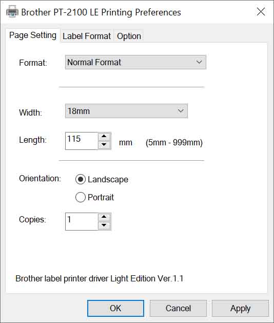
When using a label printer you will need to open the Printing Preferences dialog for your printer and set the Width to match the Print Format setting, and the Length to match the Ruler Length setting (see below). Here is an example, although your printer driver’s dialog may look different:

Print Format

The Print Format setting lets you specify a standard label tape width, or a letter-size page for printing on an ordinary printer. This deterimines the page size of the PDF document that is generated.

Upper and Lower Units

The units of each side can be specified, and if “Paces” are selected then a Pace Count can also be specified. For the Pace Count, enter the number of paces (two steps) it takes you to travel 100 meters. If you don’t know this number you can measure it by marking out a known length such as 50 or 100 meters and walking it while counting your paces. Repeat several times and average the result. You may want to print a scale with a larger pace count for rough terrain where it will take more paces to cover a given distance.

Ruler Length & Height

This is the physical size of the ruler that is printed. When printing labels it is recommended to set the Height equal to the full width of the label tape, although the printer may clip the index lines a little at the top and bottom edges. You can also reduce the height to make the ruler slightly narrower than the tape to avoid this clipping.

Map Scale

Enter the scale printed on the map, or measure the map scale if necessary. Some maps may show a scale such as 1:24,000 but may not actually be printed at exactly that scale, so it’s best to measure some features on the map to check the actual scale. To get the scale factor, just divide the real-world size of a known feature (such as the distance between two road intersections) by the physical distance measured on the map in the same units such as meters. The drop-down list at the left lets you enter common map scales easily, but you can also type an arbitrary scale into the box to the right.

Printer Scale

This lets you fine-tune the scaling to match a particular printer, because printers don’t always print things at exactly the specified size. Adjusting this is usually not necessary because measuring distances by counting paces is an approximate technique that’s affected by things such as terrain, so if a ruler is off by 1% it probably won’t matter. But if you want your ruler to be as accurate as possible then you need to experimentally determine your printer’s scale factor.

A simple way to do this is to set the map scale to 1:10,000 and the printer scale to 1.000, and print a ruler that shows a range up to 1.0km. Then measure the physical length of 1.0km on the printed scale, which ideally should be 100mm. If it is not, divide the printed length by 100mm and enter this number into the Printer Scale box. For example if it prints 98.3mm wide then enter 0.983. Try printing again and the resulting print should be extremely close. You can tweak this value experimentally, keeping in mind that making the Printer Scale larger will make the printed ruler shorter.

Mirror Image

Checking this box produces a mirror image of the ruler. This can be useful to eliminate parallax by attaching a clear label to the underside of a plastic sheet as described below.

Printing Problems?

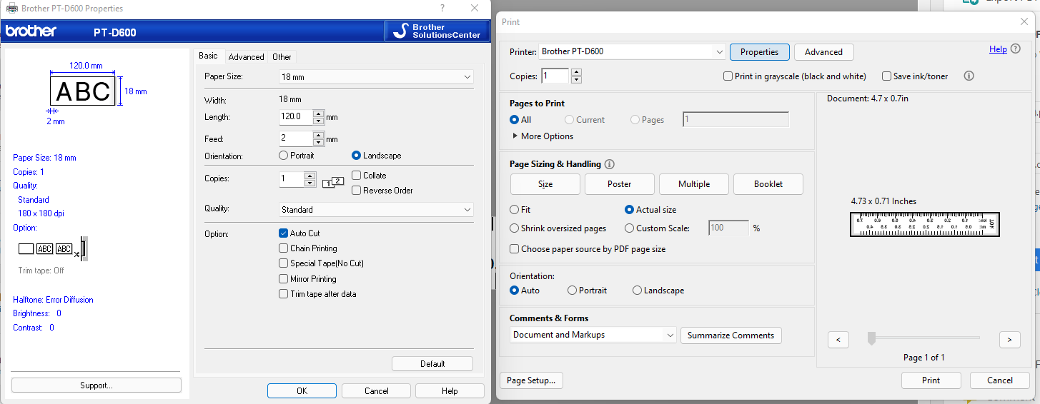
If printing directly from your browser doesn’t work right, it may work better to save the PDF document to your computer and then open it in Adobe Acrobat Reader in order to print it. You can use the ‘Download’ button in the PDF preview panel above if your browser provides one, or click the Open PDF button to open it in a new tab and then use your browser’s Save-As menu (Ctrl-S in Chrome) to save the file. Here’s an example (thanks to Bill who figured it out!) of the Brother PT-D600 properties and Adobe print dialog:

Practical Guidelines

Single-scale rulers can be printed as narrow as 6mm (1/4″), which works well for adhering directly to a compass like this:

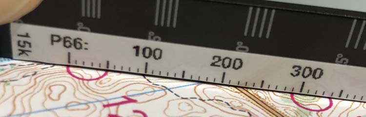
Two-scale rulers work better when printed on 12mm (1/2″) or 18mm (3/4″) clear label tape and affixed to a sheet of clear plastic:

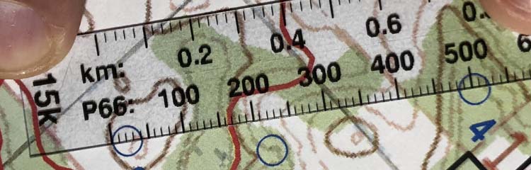
As shown in these images, you can measure paces quite accurately from orienteering maps if you align the index marks with the edges of the circles instead of the center.

The following are a few different methods to print and assemble this kind of ruler. For any of these methods, an ordinary paper punch works well to punch a hole on the right hand side (opposite the map scale) so you can keep your rulers together on a lanyard.

Easy

Use a Brother P-Touch PC-Connectable Label Maker to print a ruler onto 18mm (3/4″) Clear Label Tape, and stick the label onto a sheet of rigid clear plastic. The Mirror Image option is recommended so you can place the label on the underside of the plastic sheet, especially if the plastic is somewhat thick, because it puts the printing right on the map to reduce parallax.

A good source of clear plastic material for rulers is the clamshell packaging in which many products are frustratingly packaged, as it often has flat areas large enough to cut out ruler material. Another good source is the thin clear lids that come on things like boxes of chocolate. If you can’t find any recyclable material that’s suitable, office supply stores carry all sorts of items made of clear plastic that can be cut up and used.

Cheaper

If you don’t have a label printer, you can print a ruler onto plain paper or transparency film and then laminate it using a thermal laminator.

Cheapest

Print the ruler onto ordinary paper or heavy card stock, optionally apply clear packing tape on both sides to make it more durable, and cut it out. You won’t be able to see through it but it still works if you cut right up to the tick marks.