How To Make Custom Lens Adapters with a 3D Printer

Includes affiliate links that help offset our expenses at no cost to you.

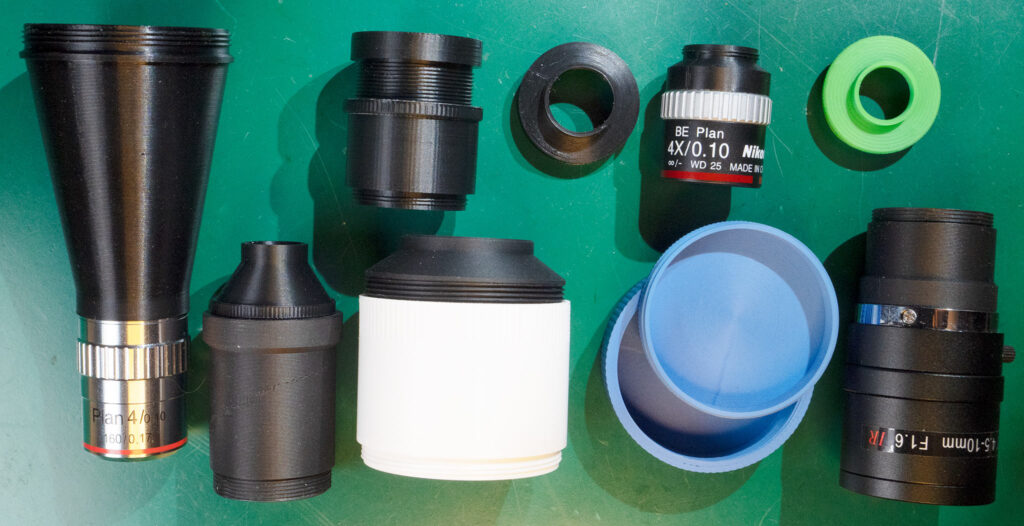
I like to experiment with new optical systems for my macro/micro videography projects, and that often means connecting together various microscope objectives, lenses and extension tubes in novel ways. It’s usually impossible to buy off-the-shelf adapters in exactly the sizes I need, so I built the Adapt~O~Matic to generate custom threaded adapters that I can 3D-print.

I was actually surprised that 3D-printed threads work for lens adapters with thread pitches of 0.75 or even 0.4mm, but they do. The finer threads take more experimentation to get the “allowance” (looseness) and the slicing parameters dialed in just right.

I use a couple of different 3D printers, a middle-of-the road Bambu Lab P1S and a higher-end Bambu Lab H2D. I really haven’t noticed much difference in quality when printing threaded adapters, and I think any mid-range 3D printer would work fine. Even a lower-end printer should work, though it might struggle with finer-pitched threads down to 0.5mm.

Making a Microscope

It’s relatively easy to turn an ordinary camera into a microscope by attaching a microscope objective, and possibly an intermediate lens. Rather than duplicate the information that’s already available, I’ll refer you to this excellent write-up on the photomacrography.net forum: FAQ: How can I hook a microscope objective to my camera?

That article explains the two main types of microscope objectives, “finite” and “infinite”, which differ in cost and complexity but are both viable options. Although most modern higher-end microscope objectives use an infinite-conjugate design, one can get very good results with simpler and less expensive finite objectives so that’s often a good place to start. I won an honorable mention in the 2023 Nikon Small World in Motion Competition using an inexpensive 4X finite objective, so it’s possible to get good results with simple and inexpensive gear.

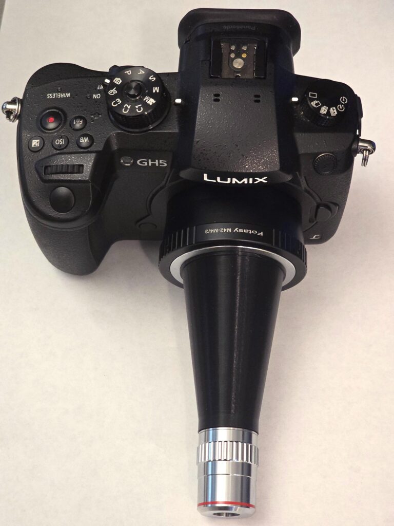
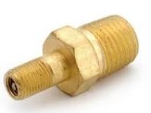
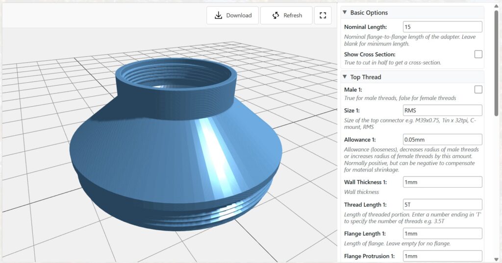
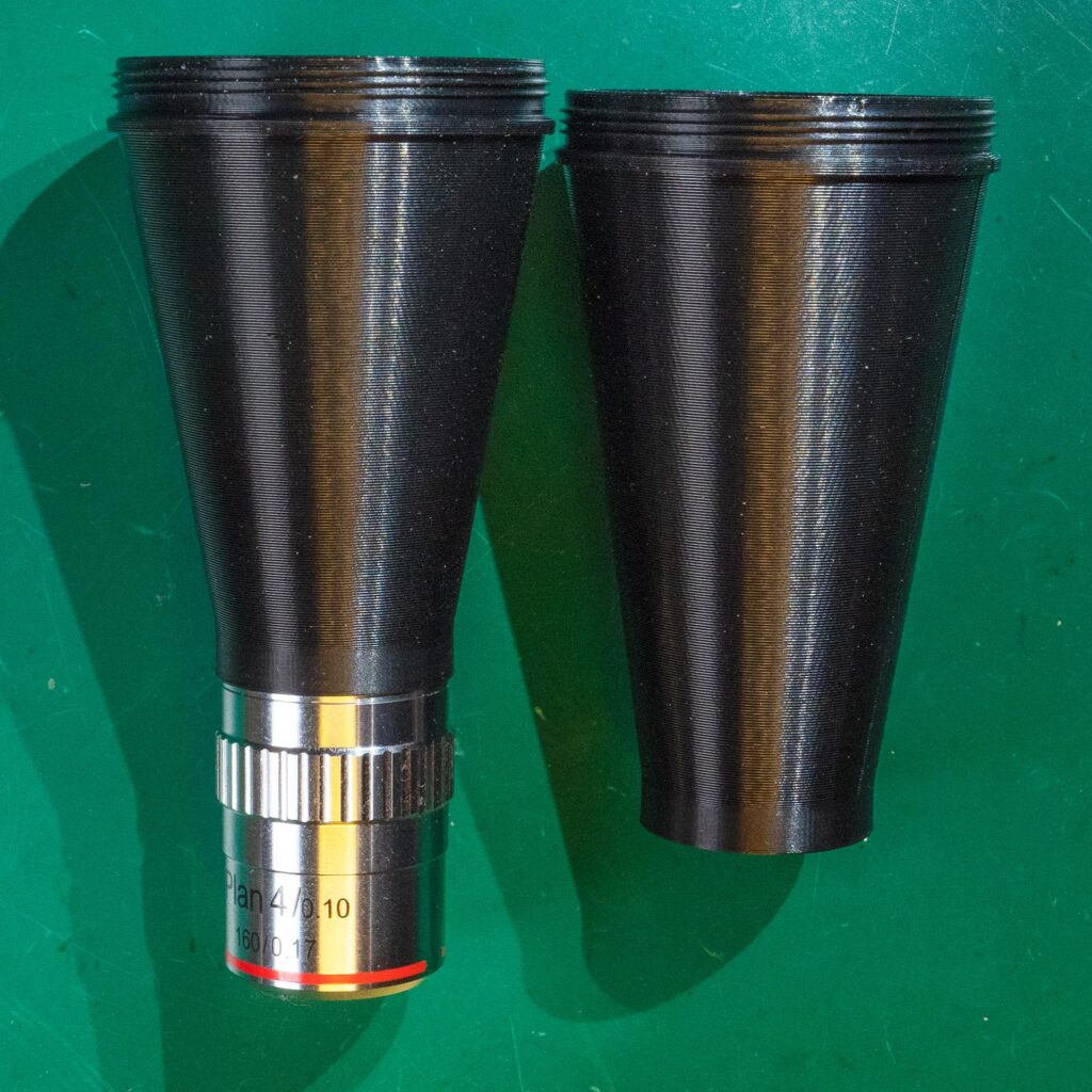
To hook a finite objective to a camera, all you need is an M42x1mm lens mount adapter for the camera plus an adapter to go between M42x1 threads and the microscope objective. That’s where the Adapt~O~Matic comes in. Most inexpensive microscope objectives use RMS threads, so you can generate this adapter simply by specifying RMS female for the top thread, and M42x1 male for the bottom thread. The Adapter Length setting is an interesting choice because it will determine the actual magnification.

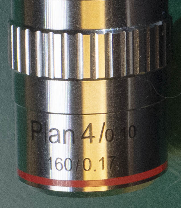
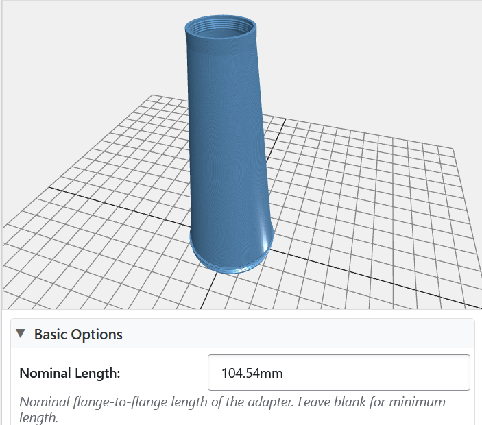
Many finite objectives will have the number 160 on the barrel, which specifies the physical length of a microscope tube for which they are designed. But the actual image is focused 10mm closer than that, meaning that placing the objective’s back flange 150mm from the camera’s sensor should give the nominal magnification such as 4X – which means that a 1mm wide subject would make a 4mm wide image on the sensor. Some objectives use other tube lengths such as 210mm, but by historical convention it’s always 10mm longer than the actual flange-to-image distance. The standard M42x1 lens mount has a flange 45.46mm in front of the sensor, so we must also subtract that in order to get the desired adapter length. For example with an objective having a 160mm nominal tube length, we compute 160 – 10 – 45.46 = 104.54mm, and that is the number to enter into the Nominal Length parameter of the Adapt~O~Matic.

Finite microscope objectives can be “pushed” up or down in magnification by using a longer or shorter distance from the sensor, and we often want to do this in order to match the image circle of the objective to the size of the camera’s sensor. Most objectives will focus an image that covers an APS-C sensor at their nominal magnification. For a larger full-frame sensor you might want to increase the magnification to about 150% of nominal to cover the sensor better, and for a smaller micro-4/3 sensor you might want to decrease the magnification to about 66% of nominal. With high-magnification objectives the image quality may suffer, but at 4X or 10X they’re usually pretty flexible in this regard.

You can achieve this just by scaling the actual flange-to-sensor distance (150mm in the example above) by the desired change in magnification. So for a micro-4/3 sensor a focal distance of 100mm is usually about right, and we subtract the M42 flange distance of 45.46mm to get a desired adapter length of 54.54mm. I’ve specified these numbers to 0.01mm but in actuality the distance is not critical, and you can experiment with different magnifications to get the best results you can.

Macroscopic and Microscopic Video Projects

I developed a process and my own custom software for creating macro and microscopic videos with a focus-stacking technique to achieve a large depth of focus at high magnification while maintaining smooth motion. These videos explore the microscopic world in a new way, as motion reveals fascinating 3D structures.

See this page for information about the CNC videography setup that I built in order to capture these videos.

This video of Self-pollination in a flower of thymeleaf speedwell (Veronica serpyllifolia) won 1st place in the 2025 Nikon Small World in Motion competition. And the video of Dissolution and crystallization of cobalt, copper and sodium chlorides won an honorable mention. Click on the pictures to see the full videos on Nikon’s website (opens in a new tab):

This shows a turquiose weevil using the AstrHori 18mm macro probe lens:

This video of water droplets evaporating from the wing scales of a peacock butterfly (Aglais io) won 2nd place in the 2024 Nikon Small World in Motion competition. Click on the picture to see the full video on Nikon’s website (opens in a new tab):

This video of thin-film oxidation on pahoehoe lava won an honorable mention in the 2023 Nikon Small World in Motion competition. Click on the picture to see the full video on Nikon’s website (opens in a new tab):

I license the music for my YouTube videos through audiio.com (affiliate link). Enter code SAVE70 to get 70% off!

Building a Macro/Micro Photography and Videography System

Includes affiliate links that help offset our expenses at no cost to you.

I designed and built this setup for macro and micro photography and videography, including a 5-axis CNC motion control system. The mechanical design would be suitable for many types of macro photography, as it is extremely rigid yet easy to adjust. It’s also easy to build, and reasonably affordable if you can find an optical breadboard at reasonable cost. The support structure could work with a less expensive aluminum breadboard or even a plywood base, although it would not be as rigid.

See this page for some videos that I’ve created with this setup.

In this Part 1 video, I go over the mechanical design that helps minimize vibration while allowing very flexible adjustment of the camera positions and angles:

Part 2 covers the CNC motion control system based on a Raspberry Pi, BigTreeTech Octopus control board, and Klipper software:

Hardware

Here’s a parts list of the hardware I used in case you’d like to build something similar:

ThorLabs Nexus B1818F breadboard (I found mine used on eBay)

Sorbothane Vibration Isolation Pads .5″ Thick x 2.25″ Dia. 30 Duro

80/20 Inc, 14081, 15 and 40 Series 4 Hole Inside Corner Bracket

1545 extrusion 18″ long, plus one piece 9-3/8″ long

Aluminum Angle, 2-1/2″ Leg Lengths, 1/4″ Wall Thickness

14-20 Threaded Knobs

1/4-20 T-nuts

1/4-20 Socket Head Cap Screws

1/4-20 Hex Socket Flat Head Screws

Arca Swiss Compatible Quick Release Plate

Motion Stages

These are the parts I used for the motion stages:

Vexta 5-phase Stepper Motors (eBay search) (my 0.36-degree steppers are great but 0.72-degree motors are also very good)

THK KR26 Linear Stages (eBay search)

THK KR20 Linear Stage (eBay search)

ThorLabs HDR50/M Rotation Stage (eBay search)

OptoSigma TASB-402 manual X-Y stage (eBay search)

Electronics

Here are the control boards, stepper drivers, and associated parts:

Raspberry Pi 3 Model B

BigTreeTech Octopus V1.1 control board

12V/24V to 5V Step Down Module with Micro USB Connector (powers Raspberry Pi from a 24V supply)

Vexta Nanostep DFR1507A 5-phase Stepper Driver (eBay search)

DM542T Digital 2-phase Stepper Motor Driver

Specimen Mounting

This is what I use to mount specimens with quick-release fittings:

27 Gauge Blunt Tipped Dispensing Needles

Krazy Fix Light Cure Super Glue

Male Luer Lock Adapters

Mini 1/4″ Ballhead

40 Dram Pill Bottles

Software

This is the software I used, and some links to resources that I found helpful:

Klipper motion control software

Mainsail user interface for Klipper

MainsailOS prebuilt image for Raspberry PI with MainSail, Klipper etc. already installed

BigTreeTech Octopus documentation repository (includes pinouts and schematic diagrams)

BigTreeTech Octopus setup guide

My printer.cfg file for Klipper. Opens as a text file in a new window.

Brackets

This is a drawing of the brackets that I made, which are the key to making the system very rigid yet also easy to adjust and capable of any angle from about 45 degrees upward to 90 degrees downward. The slot locations are designed to work with the 1545 aluminum extrusion so that they can be adjusted over the full range of angles without having to completely remove the cross-beam from the support posts. Only the top-most (angled) slots’ attachment bolts need to be shifted from one extrusion slot to another in order to go from horizontal to vertical orientation.

How to Turn an Inflatable Kayak into a Sailboat

Our Sea Eagle kayak makes a fun and very portable sailboat with a sail kit from sailboatstogo.com. It’s compact enough that we can carry it inside our camper van, and take a sailboat on our overland adventures without having to tow a trailer.

As a sailboat, it’s not high-performance but sails pretty well and it can tack upwind because of the leeboards that hang off the sides and take the place of a keel. This video was the first time we used the outriggers and they do make for a more comfortable ride with less heeling over, but they also add some drag. We probably wouldn’t use them in light wind, but we were glad to have them on this day with gusts up to 20 knots.

Diamond Drag Engraving with my CNC Router

Includes affiliate links that help offset our expenses at no cost to you.

This shows how I use my CNC Router with a diamond drag engraving bit to engrave anodized aluminum. I’m making a credit-card-sized map ruler, which I designed for Fortune Bay Expedition Team, as a trinket that we can leave in geocaches when we’re out practicing our navigation skills.

Engraving Feed and Speed

I tried a few different feed depths, which is the distance the Z axis plunges the bit “below” the surface to compress its spring-loaded tip. A depth of 0.5mm gave good results, because it didn’t apply too much pressure and was far enough that it wasn’t significantly affected by variations in the surface height. So I zeroed out the Z axis when the diamond just touched the surface, and then set the depth of cut in VCarve to 0.5mm.

After trying a range of travel speeds, I settled on 1500 mm/min as the fastest speed that gave good-looking results. This has a lot to do with the rigidity of my machine, or lack thereof, as faster speeds gave lines that had more wiggles in them. I think the diamond bit itself could give good results with a faster speed on a more rigid machine.

Vacuum Fixture Details

The vacuum fixture is made from MDF, and I sprayed it with two coats of polyurethane to seal the pores. Probably any type of clear finish would work fine, polyurethane or acrylic for example. It’s not going to seal the material perfectly but it does result in MUCH less air leakage versus unsealed MDF.

It took some trial and error to get a good fit with the 3mm diameter rubber seal, and in the end I cut the groove 2.85mm wide. That gave enough snugness to hold the rubber in place, but not so much that it was hard to put in. The side-to-side compression of the rubber squishes it up a little, so the groove is a full 3mm deep but the rubber gets squeezed above the surface in order to make a seal against the card.

Stuff That I Used

Here are links to the diamond drag bit that I used, plus the parts for the vacuum fixture and the 0.8mm thick business card blanks.

CNC Diamond Engraving Bit 90-degree

The above link takes you to this item on eBay, where the manufacturer sells it for a little less than on their own website at engravingbit.com.

RDZ Engraver For CNC Machine

This is a similar alternative that’s somewhat less expensive on Amazon. I haven’t used this one, but I would expect very similar performance.

Foam Rubber Weather Strip

I used the 3mm size for this vacuum fixture, and I also got some of the 4mm size to use for larger parts in the future.

Air Tank Valve 1/8″ MNPT

These work well for making an air outlet fitting attached to the vacuum fixture, and my vacuum pump hose has a quick connector that just clips on. Remove the valve core to use as a vacuum fitting.

Metal Business Cards Anodized Aluminum Plaque Plate 86X54X0.8mm (Blue, Blank,10PCS)

You can find much thinner blanks at lower cost, but the 0.8mm thick ones are stiff and worked better for my application.

Metal Business Cards Anodized Aluminum Plaque Plate 86X54X0.8mm (Black, Blank,10PCS)

Black is perhaps the most common color, and it’s available from many different vendors if you shop around. Just pay attention to the thickness.

Metal Business Cards Anodized Aluminum Plaque Plate 86X54X0.8mm (Green, Blank,10PCS)

Green is somewhat hard to find but it’s an attractive color.

VCarve Pro Project File

If you have Vectric VCarve Pro and want to make something similar, you may download my project file below. It was created with VCarve Pro 11.5 and may or may not work in earlier versions of the software.

Our Adventure Van

Here are some videos we made of our Thor Sanctuary 19P camper van:

CNC Epoxy Inlay Backgammon and Cribbage Board

Includes affiliate links that help offset our expenses at no cost to you.

I’m using my CNC router to make a travel-sized backgammon and cribbage board, inlaid with epoxy and colored mica powder.

Part 1 – Milling Stock, Cutting Pockets

In this first installment I introduce the project, mill the wood to size, and set up the CNC router to cut the inlay pockets on the backgammon board.

Part 2 – Backgammon Inlay

In the second installment I mix the mica and epoxy, and pour the inlays.

Part 3 – Special Details

In the third installment I add gold edges to the points on the backgammon board, and make the inlay and holes on the cribbage board side.

Part 4 – Finishing It Up

In the fourth and final installment I dye the wooden playing pieces and build the finished boxes with splined miter joints.

Resources

Here are links to some of the tools, materials and software that I’m using in this project:

AutoDesk Fusion 360 for personal use
Blender software
Next Wave CNC Shark Router
Carbide 2-flute Down-cut end-mills
Mica Powder for Epoxy Resin
West System Epoxy
Wooden checker pieces
Wooden cribbage pegs
Keda Aniline Dye 5 Color Kit

CNC Feeds & Speeds

UsageBitRPMDepth of
cut
Plunge
mm/min
Cut
mm/min
Comments
Roughing0.1250″ (3.18mm)
2-flute downcut
250003/32″ (2.38mm)500800
Finish0.0313″ (0.80mm)
2-flute downcut
250003/32″ (2.38mm)200250
Drill0.1250″ (3.18mm)
4-flute upcut
250000.25″ (6.35mm)
200n/aPeg holes
Engrave0.1250″ (3.18mm)
30-degree point
25000Variable400400V-carved text

Wood Dye Info

I dyed the playing pieces using a Keda Aniline Dye 5 Color Kit, and I mixed it following the manufacturer’s instructions but with a higher ratio of dye to water to get more concentrated colors. Here are the amounts of dye I mixed with 3 ounces of warm water:

Red: 1/8 teaspoon
Blue: 1/4 teaspoon
Green: 1/8 teaspoon yellow + 1/4 teaspoon blue
Purple: 1/8 teaspoon red + 1/4 teaspoon blue

Next time I use the blue dye, I’ll mix it with hot (not just warm) water in hopes of getting it to dissolve better.

Portable Wood Fired Pizza Oven

Includes affiliate links that help offset our expenses at no cost to you.

This video shows how I built a portable wood-fired pizza oven that’s inexpensive, easy to build, weighs only 7.5 pounds, and can be carried easily in a backpack. And it makes fantastic pizza too!

Also see our Cooking with Fire event where we used this oven along with some other great fire cooking techniques.

Materials List

Here are the materials I used to build this oven. I recommend getting these materials locally but in case you can’t, I’ve included links to amazon.com.

Tools

These are the tools I used for this project, again with links in case you have trouble finding any of these items:

How to Use a CNC Router for Shell Inlay

Here’s how I designed a shell inlay for a guitar headstock using Fusion 360, and cut the inlay using my CNC router.

Part 1 – Design in Fusion 360

Part 2 – Cutting Shell Material

Resources

Here are links to some of the tools, materials and software that I’m using in this project:

AutoDesk Fusion 360 for personal use
Next Wave CNC Shark Router
Carbide 2-flute Down-cut end-mills
1/32″ Carbide shell cutter
Phenolic backer board

CNC Feeds & Speeds

UsageBitRPMDepth of
cut
Plunge
mm/min
Cut
mm/min
Comments
Wood pocket0.0313″ (0.80mm)
2-flute downcut
250000.5mm roughing
0.2mm finish
200250
Shell0.0313″ (0.80mm)
shell cutter
250000.3mm125250

Fusion 360 Project File

Here is the Fusion 360 project file that I used for this design. It is set up specifically for my machine and cutting tools so I make no guarantees that it will work for you, but you are welcome to use it at your own risk.

DragonflyInlay.f3d

Welding Cart

Includes affiliate links that help offset our expenses at no cost to you.

I built this welding cart to hold my new Everlast PowerPro 205S TIG Welder and Plasma Cutter as well as my Lincoln MIG Welder. The cart features a large work surface and five hitch-style attachment points for mounting accessories such as a bench vise and camera supports.

Resources

I used SketchUp software (now available as a free online app) to design the cart, and here is the model file: WeldingCart.skp. You are welcome to download this model and customize it any way you like.

Here’s a link to the Menard’s Masterforce 30-inch Five-Drawer Mobile Tool Cabinet around which this cart is built.

I used a 4 in. Swivel Vise with Anvil from Harbor Freight. It’s an inexpensive vise but the quality is good enough for my purposes.

Also from Harbor Freight I bought the 8 in. Deep Throat U-Clamp and 12 in. Deep Throat U-Clamp for under $10 each. The 12-inch clamp is deep enough to reach almost anywhere on the 25-inch wide work surface of my cart. Their quality seems pretty good for the price.