Under-slab Plumbing

July 1, 2009
Today the plumbers started laying the sewer drains in the cottage. The drain runs are fairly short, and stubbed outside for a future connection to the septic tank once it’s installed.

Here’s a view of the drain lines from above. From top to bottom are the kitchen sink, bathroom sink, toilet, and shower.

We also started laying 2″ plastic conduit through which we’ll push the PEX tubing for hot and cold water supply after the slab is poured. This way is a lot easier to run the tubing under the foam insulation because the conduit stays put, and in the unlikely event that these lines ever freeze we can just pull out the old tubing and replace it. The cold water conduit shown here just runs through the sand, and the hot-water lines will run in a separate conduit with foam insulation all around it.

July 3, 2009
The plumbers finished up the under-slab drains for the main house. These lead out underneath the garage slab, and the main house drain will join the cottage drain outside before entering the septic tank.

July 5-9, 2009
After back-filling the sewer drains, the plumbers ran conduit for the cold and hot water supply lines in the main house. All the gray tubes are conduit, through which we will push 3/8″ PEX tubing to supply hot and cold water to the fixtures. The blue lines supply water to the outdoor hydrants.

We put 3″ foam insulation underneath the hot water runs. Later we’ll butt the first layer of under-slab insulation against the conduit, and then cover it with the second layer of under-slab insulation so the whole thing has at least 3″ of insulation on every side. This insulates the hot water pipes to R-15 or better below the slab.

July 9, 2009
This shows the water inlet to the cistern. We had the plumber use PVC pipe and fittings that are all rated for potable water so the pipe won’t introduce contaminants into the water. Even if we don’t use it as a potable water supply in the near term, this keeps our options open.

Slab Insulation

Includes affiliate links that help offset our expenses at no cost to you. Affiliate programs and affiliations include Amazon Associates and the eBay Partner Network.

June 25, 2009
Today the semi truck arrived from Insulation Depot carrying about 10,000 square feet of 3-inch-thick extruded polystyrene foam. It is reclaimed foam that was removed from service, possibly from a cold-storage warehouse. The sheets are 2 feet wide and 8 feet long, and they came bundled in 11 pallets of 60 sheets. Each pallet weighs a few hundred pounds. After pondering how we would get them out of the semi trailer, we decided to drag each one onto the bed of the pickup truck, then dump it off to the side. Thanks to help from Jack, Di and Nash we were able to get them all unloaded in about an hour.

Liz spent the rest of the day carrying foam sheets up to the building site. She moved 660 pieces of it! This photo doesn’t quite show it all.

June 29, 2009
Today the excavators started back-filling inside the cottage.Once they had the grade about right, we placed foam sheets vertically inside the foundation walls, making two layers 24″ high and a total of 6″ thick for an insulation value of R-30. This will greatly reduce heat loss at the edges of the heated slab.

After each section was cut and fit, they compacted the soil around the foam.

The corner joints are staggered to provide better coverage, in order to prevent thermal bridging from the warm slab to the cold foundation walls. Once the foam was all in place they dumped in more sand to bring it up to 10″ below the tops of the walls, and kept compacting it so it won’t settle under the slab. After the under-slab plumbing is in place this will be covered with a moisture barrier, 6″ of foam and then 4″ of concrete to bring the finished floor level up to the level of the foundation walls.

June 30, 2009
Back-filling continued through the front porch and entryway. We cut holes in the foam for pipes that will run through the foundation walls and under the slab.

The foam was beveled to fit around the 45-degree corners in the entryway and the dining room.

The first photo below shows the entryway looking west from inside the house, with the cottage beyond to the left and just a bit of the garage showing on the right. The second photo shows the front porch looking east as you approach the front door, with the entryway and main house beyond, garage to the left, and cottage to the right.

With the entryway done, the excavator moved in to start back filling the main house.

July 1, 2009
Today started with more back filling, inside the house and workshop and around the cistern.

The walls were back filled inside and out at about the same rate, and compacted every 12″ inside.

Once the dirt was up to 24″ below the walls, we added the foam on the inside of the main house and in the workshop. The workshop won’t be heated like the house, but we still want the slab well-insulated so it gets the same level of insulation as the house slabs. The shop will have large clerestory windows on the south and reasonably good insulation in the walls so it should maintain a comfortable temperature most of the time just from passive solar gain. Then we can warm it up when needed with a wood stove.

July 9, 2009
We used a Water Levelto level the dirt inside the cottage to about 10″ below the top of the foundation walls. That allows for two layers of 3-inch foam plus 4 inches of concrete. Once it was all level (a tiring job!) we laid the first layer of 3-inch foam over the dirt.

In order to cut the foam accurately we set up a nichrome wire powered by our 75-watt solar panel, to melt through the foam in order to cut straight lines and round cut-outs for the pipes. It worked great, except when the sun was covered by a cloud. It was partly sunny so we found ourselves watching the sky to guess when we’d get a few minutes of cutting in between clouds. The next day was mostly cloudy so we had to switch to a transformer powered by a generator. The solar panel was quiet and more fun but the generator was more reliable.

We laid down 12-inch-wide pieces of foam under the hot water conduits and flush with the dirt, and then we ran the first layer of foam up over it and against the conduit. With the second layer of foam over it all, the hot water conduits will be insulated with 3 inches of foam (R-15) on all sides. Later we’ll push 3/8″ PEX tubing through these for the hot water runs to the fixtures.

In the photos above and the one below, you can see a small reddish tube that we placed under the foam. This tube is about 10 feet long and ends in a solid plug as shown below. Later we’ll push a temperature probe down through this tube, in order to let us monitor the temperature of the dirt right under the foam. A similar tube is placed right above it on top of the foam and at the bottom of the concrete slab. By measuring the temperatures of the slab and the dirt below it, we will be able to determine how much heat we are losing through the foam. That won’t help us directly, but it will help answer the question of whether 6 inches of foam is too much, too little, or just right.

After the first layer was done, we laid the second layer with the 2’x8′ sheets running in the opposite direction to give us 6 inches of foam total. With three of us working we were able to lay all the horizontal insulation for the cottage in a day, including the time it took to make the solar foam cutter.

July 14, 2009
The insulation under the workshop was laid in two layers much like that in the cottage.

With the shop insulation in place, we started leveling the dirt in the main house. Here you can see the hot water conduits running to the bathrooms on the left and the kitchen on the right, with insulation underneath them at dirt level.

July 17, 2009
The main house required a lot of foam, which Peggy and Liz carried up to the foundation as the others laid it into place.

In the photos below you can see the first layer of foam in the house, and the area around the shower base. In this area we put only one layer of foam so it’s 3″ lower than the main slab. This will let us build a roll-in shower that sits just slightly lower than the bathroom floor.

Here you can see the shower base poured full of concrete 4 inches thick, as the rest of the second layer of foam is laid into place. We built a curb around the area that will hold the 2500 gallon water tank, which will store heat from the solar heat collectors. This serves two purposes. It insulates this little slab from the main slab so that the heat won’t leak out when we don’t want it to. And it allows this slab, which holds 20,000 pounds of water, to settle independently of the main floor slab without cracking it. Although that’s a lot of weight, it’s spread out over a large area so the pressure on the foam will be less than the pressure created by a person standing on one foot. We expect it to settle a little, but not much.

Foundation Walls

June 5, 2009
Today the crew started setting forms for the foundation walls. The second photo below shows the assembled forms for the north wall of the house, looking east. The wall will be 4 feet high and 6 inches thick.

June 8, 2009
We had some fairly heavy rain, and the cistern floor was full of water. We can tell that the floor is nicely sloped toward the sumps on the left (west), where the water is about 2 inches deep. This will make it easier to clean out the cistern when the time comes.

June 9, 2009
Today the forms for the cistern walls arrived, and the crew set them into the hole using a crane.

The following sequence shows the cistern wall forms being erected, which took most of the day. Unlike the rest of the foundation walls, the cistern walls are 8″ thick because when the cistern is empty the walls must resist pressure from the earth against them. The center wall has extra rebar so that it can resist the pressure from water when one half of the cistern is full and the other half is empty. Normally the water level will be the same in both halves, but with the sturdy center wall we can pump all the water into one side (if we start with it half full) in order to clean the cistern one half at a time without having to discard all our water.


Into the center wall running through the cistern, we had the crew place 1″ PVC pipe wrapped in bubble wrap. These are supported on form ties in two vertical rows a foot apart, with a pair of pipes every foot. The bubble wrap will (we hope) enable us to knock the pipes out after the concrete is poured, leaving two rows of holes. We will bend pieces of 5/8″ epoxy-coated rebar and mortar them into the holes from each side, forming a permanent ladder in each half of the cistern leading up to the hatchway above. That way there’s no possibility of getting trapped in the cistern without a way out. The first picture below is with the camera held inside the bottom of the wall looking east and upward, so the two closest pipes are from the near side of the ladder and the others are from the far side of the ladder. The second picture is from the top of the wall looking down through the ladder rungs.

June 10, 2009
The crew finished up setting the forms in the morning, and the concrete arrived in early afternoon. First they filled the cistern walls, which took two trucks full of concrete.

As the walls were filled they followed along with a vibrator to consolidate the concrete, in order to remove large bubbles that would create voids in the walls. The long boom of the pump truck made it easy to reach the far corners of the foundation.

As soon as the walls were filled and troweled, we set anchor straps about every 6 feet, to hold down the stud walls of the house. The first photo below shows Jay setting anchors along the east wall of the workshop, and the second photo shows Dan setting anchors in the dining room bump-out.

These photos show the completed walls of the cistern and dining room.

June 11, 2009
Today the forms were removed, and the photos below show the forms coming off the cistern and how it looks. The drips down the sides in the second photo are water from a light rain, which is good for the walls because the concrete will develop greater strength if it remains moist as it cures.

Here’s a view looking down inside one half of the cistern. There’s a bit of a mess to clean up before we can drink from it! The second photo shows an example of how the walls look inside. We need to grind down all the surface irregularities and residue from the forms before we can apply a sealer to the inside. That’s going to be a dirty job.

The first photo below shows the whole foundation viewed from the northeast corner of the workshop, and the second photo shows the dining room bump-out looking southwest.

June 15, 2009
Excavation resumed, to dig out the footings for the east and west garage walls and for the cottage.

Then the concrete crew set the footing forms for the garage and entry, and the cottage.

We fabricated the ladder steps that will be mortared in to the cistern walls, by bending lengths of #5 rebar.

The cistern walls had excess material along the form joints that needed to be ground down relatively flat. And they had a somewhat porous surface in some areas, so Jay used a rotary wire brush to remove all loose material prior to sealing. This is a very dirty job!

June 16, 2009
After pouring the walls for the root cellar, the crew moved on to pour the footings for the cottage and entry. This completes all the footings for the house.

June 18, 2009
The first photo below shows the pouring of the entryway walls. The box in the second photo is the foundation for the cottage porch, with the dining area to the right.

Notice Jay’s intense concentration as he sets wall ties into the wet concrete. These straps will anchor the stud walls down to the foundation. The second photo shows the completed foundation of the cottage and entryway. The wall in the foreground separates the garage from the main house.

Root Cellar

Includes affiliate links that help offset our expenses at no cost to you. Affiliate programs and affiliations include Amazon Associates and the eBay Partner Network.

Our root cellar is designed to provide year-round cool storage of fruits, vegetables, wine, cheese etc. without using any electricity. We designed it based on what we learned from the book Root Cellaring: Natural Cold Storage of Fruits & Vegetables and it’s about the same size and shape as the cistern so that we could use the same shoring for pouring the roof slab.

June 4, 2009
After pouring footings, the crew poured the root cellar floor.

June 16, 2009
Yesterday the crew set the forms for the root cellar walls, and today they poured the concrete.

June 18, 2009
Stripping the forms revealed the root cellar walls. The first picture below is from the hill behind, looking south. Beyond the cellar you can see part of the garage. The second photo is the front entry to the cellar, looking north. The roof will cover all of it including the entry. There are lengths of rebar poking about 12″ out the front of the entry walls, which will get tied into a stone face wall later. On the lower left in the second photo you can see the 6″ air inlet, which will draw in air through a pipe that extends horizontally to the southwest.

July 2, 2009
The excavators installed a socked drain tile around the back of the root cellar. This will allow ground water to drain away, in order to relieve pressure on the walls. It’s probably not necessary with our sandy soil but it’s cheap protection against damage from freezing or seeping ground water.

July 6, 2009
We installed the shoring that was removed from the cistern into the root cellar. This will support the concrete while the roof is being poured.

July 7, 2009
Today the crew placed lots of rebar atop the cistern shoring, and then poured the roof. They used a bucket on their crane to get the concrete from the truck up onto the roof.

In the photos below you can see two 4″ pipes sticking up near the north (closest) corners of the roof. These will be for air outlets that will extend up through the earth cover to let warm air escape. Combined with the low air inlet shown above, this will provide passive ventilation for the cellar that will let us cool it off in the fall and keep fresh air circulating. We’ll close down the air inlet during very cold weather to keep the cellar from freezing. After the slab was hard enough to walk on, we covered it with a tarp to keep it moist for the next week in order for it to cure properly.

August 15, 2009
Now that the house roof is on, here’s a view of the root cellar from above.

October 7, 2009
In preparation for back-filling, the 4″ PVC vent pipes were inserted through the holes that we formed in the roof. This is the same size pipe that was used to form the holes as the concrete was poured so it was a tight fit and we had to pound the pipes into place. We then added butyl caulk around the top to prevent moisture seepage.

October 8, 2009
The air intake is a 6-inch PVC pipe located just above the floor to the left of the door.

Once the intake vent pipe was in place, back-filling commenced. Although this looks like rich topsoil it’s actually brown sand.

They continued filling around the back, being careful not to drive equipment on the concrete roof.

After the sand was in place, a layer of topsoil was added to finish it off.

Here’s a view from above. There’s about 2 feet of soil on the roof at the front (not counting the entryway), sloping up to nearly 3 feet at the back.

October 17, 2009
The intake vent pipe was extended to a total of 40 feet, sloping it slightly so that any condensation will run out. We kept a small fan blowing air out of this pipe while assembling it and for several days thereafter, until the PVC cement fumes had fully dissipated.

October 22, 2009
Final grading of the cellar was completed today, covering the intake vent pipe with topsoil. The end of the intake pipe has a piece of fiberglass screen over it, with a pipe coupling wedged over the screen to hold it in place, and a piece of hardware cloth to protect it from chewing animals. That should keep out most types of pests. The vent caps on the roof vents are similarly protected. Eventually we plan to build a curved stone retaining wall around and over the entrance but at this point the cellar is usable for cold storage.

The Cistern

Includes affiliate links that help offset our expenses at no cost to you. Affiliate programs and affiliations include Amazon Associates and the eBay Partner Network.

Our cistern is designed to store up to 12,000 gallons of rainwater collected from the main roof surface of the house. It is divided into two chambers by a wall that runs down the middle. This wall serves to support the roof so the roof slab only needs to span about 6 feet. The interior dimensions of each half are roughly 6 feet wide by 13 feet long by 10 feet high.

June 4, 2009
Today the concrete crew poured the cistern floor with integral footings around the perimeter and across the center to support the central wall. This concrete contains polypropylene fibers that strengthen the concrete and reduce cracking. It also has a water-to-cement ratio of only 0.4 with a water reducing agent that makes it thin enough to pump, which also reduces the tendency to crack by reducing the amount that the concrete shrinks as it cures. Foam disks were inserted into the concrete to form shallow sumps from which we can pump water in order to clean the cistern, and the floor is sloped slightly toward the sumps so everything will drain into them.

After the cistern floor had hardened somewhat they troweled the surface smooth. The two foam disks will be removed later, to leave a drainage sump in each half. After it was finished we covered it with a silver tarp to reduce the rapid moisture loss from the surface, again to help reduce the tendency to crack if the concrete surface dries too rapidly.

June 8, 2009
We had some fairly heavy rain, and the cistern floor was full of water. We can tell that the floor is nicely sloped toward the sumps on the left (west), where the water is about 2 inches deep. This will make it easier to clean out the cistern when the time comes.

June 9, 2009
Today the forms for the cistern walls arrived, and the crew set them into the hole using a crane.

The following sequence shows the cistern wall forms being erected, which took most of the day. Unlike the rest of the foundation walls, the cistern walls are 8″ thick because when the cistern is empty the walls must resist pressure from the earth against them. The center wall has extra rebar so that it can resist the pressure from water when one half of the cistern is full and the other half is empty. Normally the water level will be the same in both halves, but with the sturdy center wall we can pump all the water into one side (if we start with it half full) in order to clean the cistern one half at a time without having to discard all our water.

Into the center wall running through the cistern, we had the crew place 1″ PVC pipe wrapped in bubble wrap. These are supported on form ties in two vertical rows a foot apart, with a pair of pipes every foot. The bubble wrap will (we hope) enable us to knock the pipes out after the concrete is poured, leaving two rows of holes. We will bend pieces of 5/8″ epoxy-coated rebar and mortar them into the holes from each side, forming a permanent ladder in each half of the cistern leading up to the hatchway above. That way there’s no possibility of getting trapped in the cistern without a way out. The first picture below is with the camera held inside the bottom of the wall looking east and upward, so the two closest pipes are from the near side of the ladder and the others are from the far side of the ladder. The second picture is from the top of the wall looking down through the ladder rungs.

June 10, 2009
The crew finished up setting the forms in the morning, and the concrete arrived in early afternoon. First they filled the cistern walls, which took two trucks full of concrete.

As the walls were filled they followed along with a vibrator to consolidate the concrete, in order to remove large bubbles that would create voids in the walls.

June 11, 2009
Today the forms were removed, and the photos below show the forms coming off the cistern and how it looks. The drips down the sides in the second photo are water from a light rain, which is good for the walls because the concrete will develop greater strength if it remains moist as it cures.

Here’s a view looking down inside one half of the cistern. There’s a bit of a mess to clean up before we can drink from it! The second photo shows an example of how the walls look inside. We need to grind down all the surface irregularities and residue from the forms before we can apply a sealer to the inside. That’s going to be a dirty job.

June 15, 2009
Jay used an electric angle grinder to grind down the seams. The walls also had a somewhat porous surface in some areas, so he used a rotary wire brush to remove all loose material prior to sealing.

June 20, 2009
In order to support the weight of the concrete roof as it is poured, we built wooden shoring. This must support a total weight of about 16,000 pounds of wet concrete so it was engineered using the design process outlined in Concrete, Masonry and Brickwork: A Practical Handbook for the Homeowner and Small Builder (Revised 1998 Edition) published by the U.S. Army. In addition, all the shoring had to be extracted later through a 2-foot-square hole without cutting it up so that we could reuse it in the root cellar, and that made the design a bit more challenging. In each half of the cistern we built two stud walls with studs 2 feet on center. Then we made 2-foot by 6-foot “tables” that were placed atop the stud walls. Here’s a view of the walls in place from above, and a view of the tables looking up from inside. Note the ample cross-bracing to stiffen the 10-foot studs so they can’t bend when compressed.

June 26, 2009
With the shoring in place, we laid down polyethylene sheeting and then the concrete crew placed a grid of heavy rebar 12″ on center across the top. We also placed a form around the hatchway, with pink foam added in order to form a recess around the edge to support the hatch cover later.

The concrete crew poured the 6″ thick roof slab, and used a power screed to vibrate and consolidate the concrete.

As soon as the concrete was hard enough to walk on, we sprinkled straw on the top and then covered it with plastic sheeting. This will keep it moist while it cures, and the straw imparts an interesting pattern in the finished floor. This will be the floor of the sun porch eventually.

July 9, 2009
To let water into the cistern we ran a 4″ PVC pipe from the north side of the house and under the main floor slab. We made sure to get fittings and pipe that are rated for potable water, rather than the drain/waste/vent pipe commonly sold at home centers. The potable-rated pipe was only a little more expensive, and it gives us some measure of comfort that the pipe won’t introduce harmful substances into the water. This 4″ pipe is sufficiently large to handle the runoff from all but the most extreme rainstorm, in which case excess water may run harmlessly along the back of the house where the ground is sloped to drain into the valley. An overflow pipe on the south, not shown, prevents the cistern from overfilling.

October 5, 2009
We fabricated the ladder steps that will be mortared in to the cistern walls, by bending lengths of #5 rebar.

In order to seal the rungs and to avoid introducing any harmful substances into the water, Bruce applied two coats of potable water approved epoxy paint. This encapsulates the rungs in an extremely tough coating that is approved for contact with potable water.

October 7, 2009
We used Quikrete Precision Grout to anchor the rungs into the holes we had created in the cistern walls. Each half of the cistern has a set of rungs like this, forming a permanent ladder. They also serve a secondary purpose as a water gauge, since they are spaced exactly 1 foot apart. Assuming that the water level is the same in both sides, as it is designed to be, each foot of water equals about 1200 gallons. We’ll collect that much from about 1/2″ of rain on our roof. We also used the same grout to seal the bottom corners of the walls.

October 12, 2009
Bruce started applying the first coat of Thoroseal to the inside of the cistern. This is a waterproof cement-based coating that is approved for use in potable water tanks. As specified by the manufacturer, we mixed it with Acryl 60 acrylic additive to improve adhesion and curing. We used a rate of 1/2 gallon of Acryl 60 per 50-pound bag of Thoroseal, about 1:3 Acryl to water. These photos show him spraying it on with a drywall-type sprayer gun and then brushing it in with a masonry brush to make sure all the irregularities are filled. The resulting rough brushed surface will help the second coat to bond well to the first.

October 20, 2009
After two coats of Thoroseal had been applied to the ceilings and walls, Bruce applied two coats to the floors using a paint roller with a 3/4″ nap. This completes the sealing of the cistern and it should be very watertight. It took a total of 12 fifty-pound bags of Thoroseal, plus 6 gallons of Acryl 60 additive.

Footings

June 3, 2009
The concrete contractors arrived today and set up forms for the footings in the house walls and the cistern. The first photo below shows the forms for the house footings around the dining room bump-out on the south. These are about 4 feet below the house floor level. The second photo shows the cistern footings, which are 10 feet below the house floor level. The footings and slab floor will be poured together, so the floor is just thicker where the footings are. These will support the walls at the edges plus a wall running east-west across the center that divides the cistern in two. The cistern will hold about 12,000 gallons of rainwater.

June 4, 2009
Today they poured the first concrete, including all of the footings dug so far plus the floor slabs for the cistern and root cellar. Because the north side of the house is not easily reachable by concrete truck, they used a pumping rig to pump the concrete from the truck to the forms.

First they poured the cistern floor with integral footings around the perimeter and across the center to support the central wall. This concrete contains polypropylene fibers that strengthen the concrete and reduce cracking. It also has a water-to-cement ratio of only 0.4 with a water reducing agent that makes it thin enough to pump, which also reduces the tendency to crack by reducing the amount that the concrete shrinks as it cures. Foam disks were inserted into the concrete to form shallow sumps from which we can pump water in order to clean the cistern, and the floor is sloped slightly toward the sumps so everything will drain into them.

Once the floor was poured they moved on to the footings. The first picture below shows the pumping rig delivering the concrete, and the second photo shows the footing forms around the dining room bump-out on the south side of the house.

Once the footings were done, they moved back to the cistern floor which was somewhat hard by now, in order to trowel the surface smooth. The two foam disks will be removed later, to leave a drainage sump in each half. After it was finished we covered it with a silver tarp to reduce the rapid moisture loss from the surface, again to help reduce the tendency to crack if the concrete surface dries too rapidly.

The first photo below shows the footings from the southwest corner of the garage, looking east. The second photo shows the same footing from the other end, looking west from the dining room.

The photos below show the back (north) wall of the house, first from the northwest corner of the garage looking east, and then from the northeast corner of the workshop looking west.

Here’s a view from the northeast corner of the house. The central area will become the workshop, and beyond it is the lanai on the left and the cistern on the right.

Excavation

May 29, 2009
The excavators dug a root cellar area just north of the house, and this provided sand for grading the rest of the site. The building pad is graded to the level that will support the 6-inch foam insulation under the 4-inch concrete floor.


June 2, 2009
After the site was mostly graded, they dug footings for the house walls. The digging uncovered lots of big rocks, which we piled off to the side to use in landscaping. The cistern is dug about 10 feet deep. A concrete floor with integral footings will go at the bottom.


Site Work

The building site started as a tangled mess of brush.

April 11, 2009
We began clearing brush using a rented 25-horsepower wood chipper and help from our nephew Nash. He’s not really taking a shower in the wood chips even though it looks that way. After a day of hard work we made what seemed like a lot of progress but there was still a LOT of brush left.

April 28, 2009
We got professional help from Absolute Tree Service. Their bobcat with a hydraulic grapple and a 200-horspower chipper made short work of trees and brush.

At the end of the day the building site was essentially clear of brush, and we ended up with about 100 cubic yards of wood chips for making paths.

Portable Bowl Lathe Construction

Raw Materials

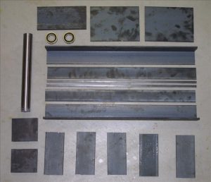
I ordered most of the steel I needed from Metal Express and they have a branch nearby so I avoided shipping charges. I ordered the 2” ball bearings and the1.5” drill rod that I used for the lathe spindle from Enco. Here’s a picture of the steel plates and angles, plus the bearings and the drill rod for the spindle.

Preparing the Pillow Blocks

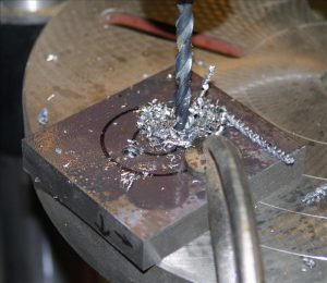
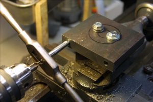
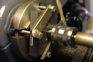
Because the steel was rough-cut I needed to flatten the bottoms of the pillow blocks, and then drill and tap them for 3/16” bolts. I drilled a couple of holes in them in order to mount them to the top slide of the metal lathe. This was an easy and solid way to mount them, although it made it harder to bore the bearing holes later. I squared them as best I could to the headstock to minimize how much I’d have to cut.

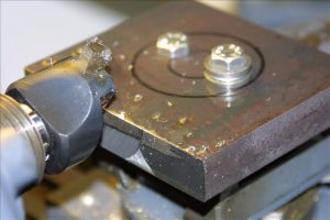
I used a fly cutter to flatten the bottom face of each block so it would sit solidly and squarely on the headstock.

I drilled and tapped holes in the bottoms for 3/16 bolts to hold them to the headstock.


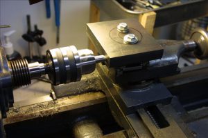
I drilled 4 bolt holes in the top plate of the headstock in order to attach the pillow blocks. I drilled them a bit oversize (7/16”) so I’d have some room to slide the pillow blocks around in order to align them.
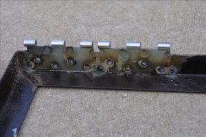
Welding the Bed

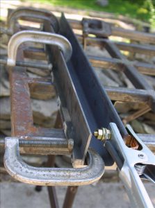
I started welding the bed by attaching the 3/8” square clamping strips to the 2” angle. These strips make the top of the bed the same thickness (5/8”) as the bed on my Jet lathe so that I can interchange the tool rest and tailstock between the two lathes without having to adjust the clamps. They don’t have to take any force and the inner surface will have to be ground smooth so I just tack welded them in several places. In the photos below, the angle is on its side so that what will become the top surface of the bed is to the right.


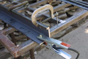
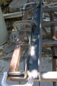
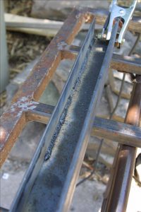
Then I welded on the 1/8” support strip that goes between the top of the bed and the cross plates on the bottom. In the photos below the piece is upside-down so the top surface of the bed is on the bottom. First I tack welded it on the inside just to hold it in place, then I went back and welded a continuous seam all the way down (the third photo shows it welded partway).

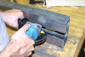
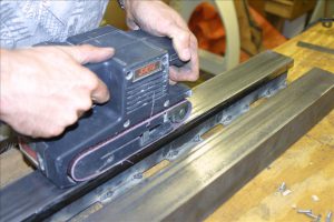
The inner surface of the ways must be ground flat so that the tool rest and tailstock can slide along it. I ground it approximately flat at this stage, but more grinding will be needed later to get the spacing just right.

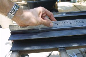
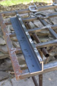
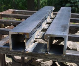
After both halves of the bed were welded up, I laid them out with spacer blocks in between to get the spacing right. I made the spacer blocks just a little short, so that the gap between the halves was just a little too narrow for the tailstock to slide in. This way I can grind it afterward for a good fit. Then the bottom support plates are laid on and welded.

You can see below that the support strip on the left twisted a little so it’s not quite vertical – a cosmetic flaw but it won’t affect anything. By design, the gap is a little too narrow for the tailstock to slide in. I got a good sliding fit by carefully grinding the inside surface, checking often for straightness and the right gap. Then I sanded down the top surface of the ways, just enough to make them smooth (but not perfectly so). The tool rest and the tailstock fit reasonably well. I ended up with just a little side-to-side playin the tailstock, from grinding the insides of the ways a little more than necessary, but it won’t have much effect on the operation of the lathe.

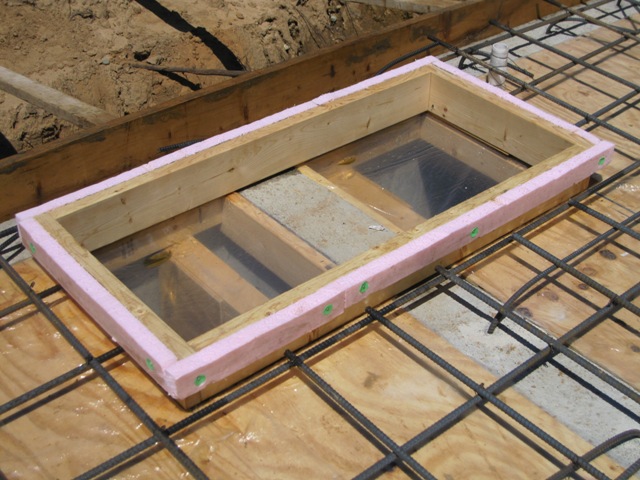
Welding the Headstock

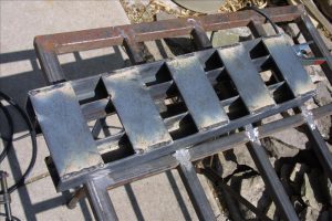
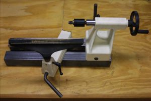
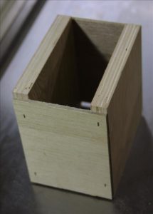
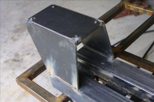
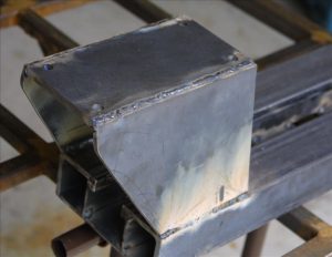
In order to position the top plate of the headstock correctly I made a wooden spacer box. With the top plate resting on this box I aligned the top plate using the tailstock so that it was accurately centered and lined up along the axis of the lathe. This is not a critical alignment because the bearing holes in the pillow blocks aren’t bored yet. I laid up the angled sides of the headstock and tack welded them together, then I removed the box and welded everything solidly. My welds aren’t very pretty, but at least they’re strong. I ground down the welds on the top plate so that the pillow blocks will sit solidly on the plate surface.

Marking the Pillow Blocks

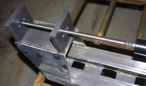
I bolted the front pillow block to the top plate, positioning the bolts about in the middle of the oversize holes in the plate so I’ll have a little wiggle room in all directions. Using the tailstock I marked the center of the block and then precisely bored a ½” hole in it. I made an “arrow” out of ½” drill rod and turned it to a point at one end. This goes from the center in the tailstock, through the hole in the front pillow block to the rear pillow block. I marked where the point touched as the center of the rear bearing.

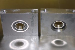
Boring the Pillow Blocks

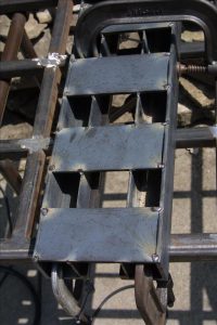
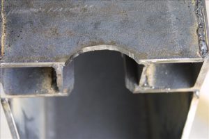
I bored out the 2” holes for the bearings, leaving a narrow shoulder against which each bearing will seat. It took a long time to bore them out, and the mounting holes I drilled earlier made it a bit rough until I had bored past them. I tried to get a close fit but loose enough for the bearings to slide just a tiny bit to help alleviate any axial misalignment of the blocks when mounted to the headstock so the spindle wouldn’t bind. The fourth picture below shows the blocks upside-down (with the bolt holes on the top); the one on the left shows the front side where the bearing slides in and the one on the right shows the back side where the bearing seats against the shoulder. I made sure the shoulder was narrow enough that I could drive a bearing out by tapping on the outer race.
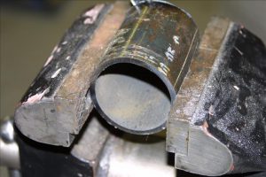
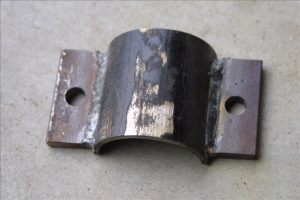
Making the Clamp

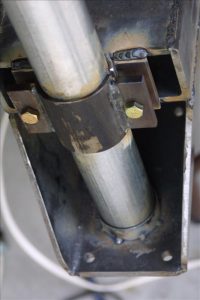
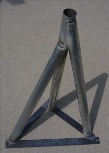
The headstock clamps on to a vertical support post, with the top of the post fitting into a tapered receiver under the top plate. I made the clamp from 2” black steel plumbing pipe, and the inside diameter is a bit too small to fit around the 2” conduit of the support post so I flattened it slightly before cutting it apart. The outer part of the clamp has two wings welded to it, with slightly oversized (7/16”) holes for the 3/8” bolts. I bored the receiver with a 3-degree taper so that it fit snugly around the conduit at its narrow (top) side.


Welding the Clamp

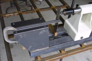
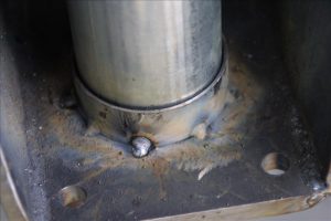
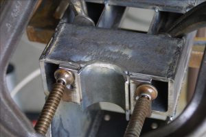
The plate on the bottom of the bed is notched to fit the clamp. I leveled the bed and then used a level to align the clamp and the receiver before welding them on. I just tack welded the receiver in several places to avoid distorting it too much. Beside the clamp on the back of the bed I welded two wings with 3/8” tapped holes for the bolts. In these photos the headstock is upside-down.

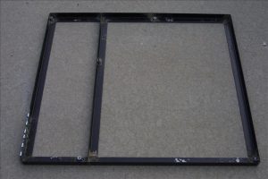
Making the Base Frame

I welded up a frame for the base from some 1/8” thick, 1.5”wide steel angle I recycled from an old bed frame. This later turned out to be too flimsy so I ended up welding on ¼” plates to the outside. It would have worked better if I’d started with ¼” thick angle instead. The center brace of the frame will extend right beneath the posts that support the headstock and tail of the lathe. Onto the frame I welded 3/8” coupling nuts, which were 1.75”long cut in half to make nuts about ¾” long. These are welded at 5 points on the frame to make the attachments for the legs. I used loose-pin hinges for the motor mount, drilled out (very slightly) to accept a ¼” rod through both hinges. The hinges are welded onto the base frame where the motor will attach, with the hinge rod through both of them while welding to keep them aligned.
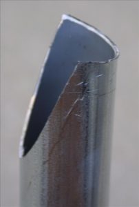
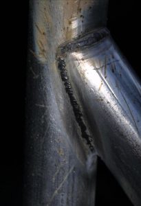
Making the Legs

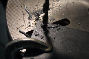
I made the legs from 2” thin-wall electrical conduit because it’s cheap (about $1/foot at Home Depot), reasonably lightweight, and quite stiff. In order to join the tubes I had to cope them, and I determined the profile using a wye joint calculator that I originally created for making Y branches in my dust collection ducts. I set the duct diameters to 2.2” and entered the angles I needed, and printed out the branch duct profile that I marked on the end of the tube. Then I just cut the profile with a saber saw. I got a pretty good fit, but I had to bend the “wings” out a little to account for the inner diameter of the branch tube mating to the outer diameter of the main tube. I welded the tubes to 3/8”thick by 2” wide steel plates at the bottom, through which I drilled the bolt holes for attaching to the base (I cut and drilled these plates and made sure they bolted to the base before cutting the tubes). While welding these tubes I made sure to avoid breathing any zinc fumes from the galvanized coating.

Making the Spindle

I made the spindle from a 12.5” long piece of 1.5” W-2 drill rod. I chose W-2 steel simply because I happened to have some, but I didn’t heat treat it in any way. First I squared off each end and drilled center holes so I could mount it between centers.


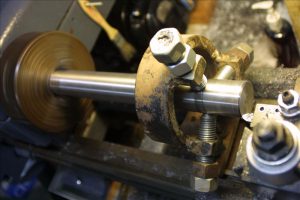
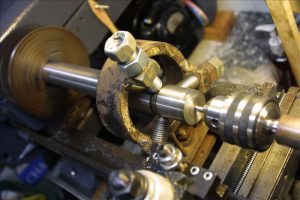
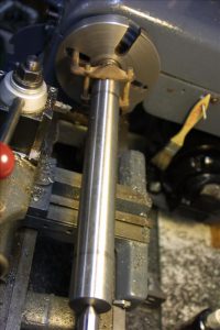
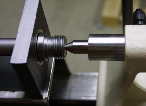
I cut a shoulder to mark the end of the main shaft, where the flange will seat against the front bearing. I turned the main shaft down to a little under 1” diameter in between the bearing areas, and then turned it to exactly 1” at the bearing points, using the bearings to check the fit often. I used some 320-grit wet/dry sandpaper to finish the surface for a nice snug fit in the bearings. I turned the end of the spindle down to ¾” to fit the sheave for the drive belt.

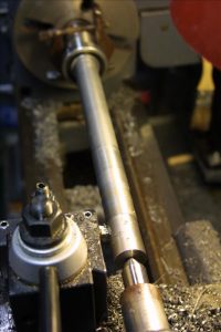
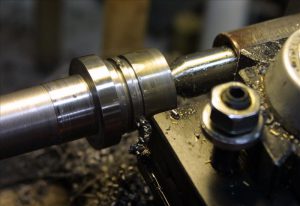
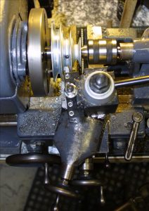
The spindle nose is threaded to match my Jet lathe so that I can use the same faceplate and chuck. Beyond the threads is a “locking groove” for the set screws of the faceplate or chuck, and I just turned this to match the dimensions of the Jet spindle. I cut the threads by angling the top slide to 30 degrees (half the 60-degree thread angle) and advancing the cut using the top slide rather than straight in using the cross slide. This is a technique I learned from The Amateur’s Lathe that puts a lot less stress on the lathe than feeding the threading tool straight in.

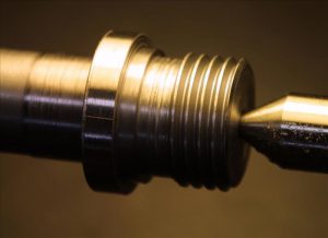
This completes the spindle. I did not bore it out for a Morse taper because I don’t need a drive center for bowl making. If I ever need a drive center I’ll make one that threads onto the spindle, which should be considerably simpler than drilling through the spindle and cutting an accurate inside Morse taper. Having a solid spindle also precludes using a vacuum chuck but if I ever want to use one I could still drill a small hole through the spindle.

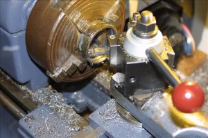
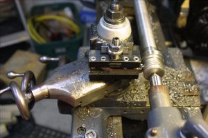
Truing the Motor Pulley

I bought a fairly cheap step pulley for the motor shaft and it was not very well made, with molding flash in the grooves and a poor finish. I put it on the lathe and trued it up by setting the top slide angle to match the groove angle (17 degrees) and taking a light cut across each face.

Aligning the Bearings

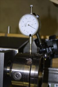
With the spindle mounted on the headstock I aligned the front bearing by centering the spindle on the tailstock center. To align the rear bearing I mounted a wooden dowel in the chuck and rotated it to determine the center of rotation out on the dowel end (which need not be in the center of the dowel). If everything is aligned correctly the center of rotation will meet the tailstock center, and I shifted the rear bearing side-to-side to align it horizontally. I expected that I would have to shim one or both pillow blocks to get things aligned vertically, but it came out extremely close without any shims. I found that the spindle rotation got a little tight when I tightened down the bolts, because the bottoms of the pillow blocks were not fly-cut exactly square to the faces. I expected this and figured I’d have to shim them a little to get them square. One thickness of aluminum foil under the rear edge of the front pillow block did the trick. I checked the spindle run out with a dial indicator on the edge of the chuck and it was only 0.001” worse than my Jet lathe. Not too bad for a first try, and plenty good enough for making wooden bowls!
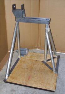
Mounting the Motor

I bought a 1-HP motor at Fleet Farm, and spent a bit extra for a ball-bearing motor so that the belt tension won’t prematurely wear out the bearings. I mounted the it to a 11”x14” piece of plywood and attached the hinges at the back. I wired in a power switch and a reversing switch so I can reverse the motor while sanding. I found a decent and reasonably cheap 20-amp power switch at Woodcraft, and removed the outlet so I had a place to mount the reversing switch. I welded some tabs on the rear lathe support leg so I can just hook the switch box to the leg and remove it easily for transport.
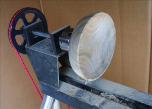
Making Bowls!

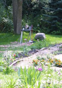
I set up for a first test in the garage, and turned a 10”bowl out of catalpa. It’s a fairly low-density wood so this was not a severe test of vibration, but I found that the lathe vibrated quite a bit until I got the blank trued up. After that it wasn’t too bad and I was able to turn a decent bowl. I moved the lathe out into the yard to see whether it would be less vibration-prone when sitting on grass instead of concrete (where the uneven surface means the base doesn’t make contact all the way across). It was a bit better on grass and I turned a larger 12” bowl, which came out pretty good. There was still quite noticeable vibration when the blank was rough and not balanced, and it seemed that part of the problem was that the base was too flexible so I welded ¼” thick by 1.5” wide steel all around the outer edge and across the center brace of the base frame to stiffen it.

I also found that the belt slipped when rough-turning the blank at the low speed (with the smallest pulley). The weight of the motor just wasn’t enough to hold sufficient belt tension so I added a clamp to the support leg that will hold the motor board down and provide enough tension on the belt.

Painting

Once I was satisfied that I wasn’t going to be altering the base or the lathe body, I primed all bare metal on the base frame and the lathe body using a metal primer and then painted them with two coats of a rust-inhibiting spray enamel. First I removed the spindle and bearings and masked off the inner surfaces of the pillow blocks with high-quality masking tape. I also masked off the top surfaces of the lathe bed.

Portable Bowl Lathe

Includes affiliate links that help offset our expenses at no cost to you. Affiliate programs and affiliations include Amazon Associates and the eBay Partner Network.

I love my JET 1462 Lathe but it’s in the basement, and unless it’s raining or snowing I really prefer to spend my time outside. I’ve dreamed of being able to turn bowls outdoors in the garden, to enjoy the nice weather and to create bushels of wood shavings right where they will be used on the garden paths rather than spraying shavings all over my basement shop. But my Jet lathe weighs about 500 pounds and it’s just not practical to move it anywhere. So I designed and built this portable lathe that is easy to move around, yet still has the capacity to handle big bowl blanks up to 16” in diameter.

Design
Firstly I wanted it to be portable, with no piece weighing over 50 pounds so I can easily carry it out to where I want to work. The lathe body and the base ended up weighing almost exactly 50 pounds each, with the motor weighing about 35 pounds and the legs around 20. It also had to be quick to set up and take down, and I can set it up in under 10 minutes including the time to carry each piece out to where I’m going to work.

I designed the lathe primarily for turning bowls so it has a short bed, just long enough to handle good-sized bowl blanks and to let me use a tailstock for holding bowls against a jamb chuck for turning the bottom. It could also handle spindles up to about 10” long but I didn’t make it for spindle work. There are plenty of commercially-available mini lathes that work fine for spindles and are easy to transport, but you won’t find many 16” bowl lathes that you can easily carry around.

I considered making it bigger, perhaps to handle blanks up to 20” in diameter, but I decided to make it with the same geometry as my 16” Jet lathe so that I can use the same tool rest and tailstock and avoid the expense and time of making them. Having a 16” capacity lets me make finished bowls up to about 14” diameter which is a good practical size, and it would have been difficult to make it heavy enough to swing bigger pieces of wood yet still easily portable.

I made the spindle threads the same as on my Jet lathe so I can use the same faceplate and chuck. I decided to go with a solid spindle rather than trying to bore a Morse taper, which made the spindle construction much simpler. That means I can’t use a drive center in the spindle but I don’t need one for bowl making anyway (although I could easily make a thread-on drive center if I ever decide I need one). I also can’t use a vacuum chuck unless I bore a hole through the spindle but at this point I don’t have any plans to do that since I don’t have a vacuum chuck. Most of the time I make green-turned bowls for which I don’t even need the tailstock, just a faceplate and a scroll chuck. When turning outdoors, the fewer accessories I need the better.

In order to make a lathe stable while swinging a big out-of-balance piece of wood one wants it to be heavy, but of course that’s not good for portability. Therefore I made the base of the lathe a platform that I can stand on, to use my own body weight to help stabilize the lathe. At the moment that adds about 155 pounds to the base, but as I get older the lathe will probably get more stable. 🙂  I made the bed the same height (above the platform) as my Jet lathe so that my posture is the same when I’m standing at either lathe.

To keep the drive simple I went with a three-step pulley (2-3-4”) on the motor and an 8.5” sheave on the spindle. With a 1725 RPM motor this gives me three speeds of about 400, 600 and 800 RPM which I find is a good range for bowl making. I start turning the blank at 400 RPM to get it reasonably balanced, do most of my turning at 600, and sand at 800. The 1 HP motor has plenty of power because unlike my variable-speed Jet lathe, the motor runs at full speed all the time. I mounted the motor down on the base to help stabilize the lathe, and I used a link belt to minimize vibration and to make it easy to get exactly the length I needed. It’s also long enough that I can shift it to any of the 3 steps on the motor pulley without much misalignment, and because the motor is on a hinged platform I can change speeds in about 30 seconds. I didn’t enclose the belt so it is a potential hazard, but I figure it’s less hazardous than the big piece of wood turning right in front of me. The most dangerous part of any tool is, of course, the operator.

Since this is meant to be used outdoors I bought a 25-foot, 12-gauge extension cord to use as the power cord. By wiring this to an outlet box on the motor base, I also have two outlets to provide power for a sharpener and if necessary, a fan to blow away dust while sanding. I’ve been using it with an additional 85-foot, 12-gauge extension cord and it seems to work fine. I haven’t yet measured the voltage at the motor while it’s under load but it doesn’t seem to be getting unduly hot so I expect that the voltage drop is minimal.

Click Here for Detailed Construction Sequence