Ventilation

October 7, 2009
The house will be ventilated with a heat recovery ventilator (HRV). In cold weather, it will transfer most of the heat from the warm outgoing air to the cold incoming air, saving roughly 70% of the heat that would otherwise be lost. In warm weather it does the opposite, cooling the warm incoming air to reduce unwanted heat gain. The HRV has 6-inch ducts for incoming and outgoing air, but our calculations of airflow resistance indicated that using 7-inch ducts throughout the house would significantly reduce the energy needed to move the air. In other words, by using 7-inch ductwork we can use a lower fan speed on the HRV to get the same airflow, reducing its energy consumption compared to what it would take if we used 6-inch ductwork. We installed intake ducts to remove stale air from the kitchens and bathrooms, and supply ducts to provide fresh air to the bedrooms and living room. The 7-inch ducts terminate at 8-inch openings like this:

October 8, 2009
As soon as the ducts were installed, we sealed up the openings to keep out dust during construction.

Dan and Liz applied duct mastic to all of the joints in the ductwork and to the seams around the elbows. This seals them better than duct tape, and it will prevent heat loss into the attic as well as prevent dust infiltration from the cellulose attic insulation.

December 20, 2009
The fresh air intake is located under the eave on the north side of the house, well away from any chimneys and exhaust outlets so that it will provide fresh air. After making the intake plenum out of plywood, Dan lined it with aluminum flashing and caulked all the seams. Then we sealed it up during construction to keep dust out.

March 2, 2009
This shows the Lifebreath 155 MAX heat recovery ventilator, installed in the mechanical room. The short insulated sections are 6-inch flexible ducting, which reduces noise from any vibration that the HRV might otherwise transfer to the metal ducts. The insulation here is for noise reduction, not for preventing heat loss, and the ends will be taped up shortly. The gauges mounted on the wall to the right of the HRV let us monitor the airflow, and they help ensure that the intake and exhaust air flows are balanced. At maximum speed we get about 120 cubic feet per minute, which is well above the minimum 90 CFM that is required. The intake gauge will also indicate when the filter needs to be changed, because it will show a reduction in airflow as the filter gets dirty.

March 13, 2009
The photos below show the Accumulair Diamond air filter and how it fits into the intake housing under the north soffit. The large filter area, compared to the 7-inch duct diameter, means that we shouldn’t have to change it very often. The filter is rated MERV-13, which is about as good as one can get in a furnace-type filter.


Foam weather stripping prevents air leakage around the edges of the filter and the sealing block shown on the right in the photo above holds it snugly against the weather stripping.

Building a Glass Crusher

DISCLAIMER: This page documents what we did, but we’re not suggesting that you should do anything like it. This machine can cause severe bodily harm, and if you use this information to build anything then you assume full responsibility for the consequences.

We converted an old clothes dryer into a crusher for crushing glass down to pieces small enough for making countertops. The basic idea is to drill holes in the drum so the broken pieces can fall through, and to make an opening the bottom so they can fall into a bucket below the dryer.

October 3, 2009
The first step was to remove the top and front of the dryer, and then to add some reinforcements to the side of the case. This is a view looking downward, with the dryer laying on its back. The drive belt runs around the middle of the drum and the motor sits behind that, so we decided to put a vertical “fence” made of plywood below the middle of the drum and to enable the crushed glass to fall out in front of that. The fence sits in front of the 2x4s shown in this photo. We added some slanted plywood sides to make a “funnel” that will guide the broken glass to the middle, where we cut a hole in the bottom of the case. Notice the plastic fins inside the drum. These are fine for tossing clothes around but they’ll quickly get smashed once this is full of bottles and rocks so they have to go.

Once we had cut the 8-inch-square hole in the bottom of the dryer and boxed around it with plywood, Dave drilled 5/8″ holes in the drum so the crushed glass can fall through and out the bottom.

We replaced the flimsy plastic fins with square steel channels bolted on to the drum. For the first short test we put in just a few bottles plus a fist-size rock to help smash them up. These photos show the glass before and after running for a minute or so. It works pretty well for a first try!

October 5, 2009
After a few test runs we decided that the holes needed enlarging from 5/8″ to 3/4″, in order to let slightly larger pieces of glass fall through. We also added another steel bar for a total of 4 bars instead of three, arranged symmetrically around the drum. The most significant refinement was to remove the heater from the back of the dryer, leaving an oval opening near the top of the drum large enough to feed bottles in while the crusher is running. Now we don’t have to stop it except to empty the glass bucket at the bottom when it’s full (it holds about 40 pounds of crushed glass).

In addition to letting us feed glass in while the crusher is running, the opening in the back of the dryer allows us to watch the crushing process – and so can you! The following is a video shot through the port on the back of the dryer as the crusher is running. For a realistic sound effect while watching the video, turn your computer’s speakers to maximum volume and then repeatedly slam them together as hard as you can right in front of your ear. It’s louder than that.

In our first production run it produced 70 pounds of crushed glass in about 15 minutes. That may sound like a lot, but our countertops will be about 85% glass and weigh about 18.5 pounds per square foot, so 70 pounds of glass will make roughly a 2-foot by 2-foot section of countertop. We’re going to need a lot more glass! Here’s a shot of the crushed glass we produced, with a dime added for scale. This is all clear glass, but you can see that some of it has light shades of blue and green. The pieces range from dime-sized down to dust, which will make stronger concrete than if the pieces were all of the same size.

Countertops

Includes affiliate links that help offset our expenses at no cost to you. Affiliate programs and affiliations include Amazon Associates and the eBay Partner Network.

We decided to make our own countertops out of concrete, using recycled glass for the aggregate. We found the book Concrete Countertops: Design, Form, and Finishes for the New Kitchen and Bath to be inspiring and helpful for getting started. Most of that book talks about making countertops out of conventional concrete, i.e. with cement and sand and gravel, but we like the look of glass aggregate. Here are a couple of examples from Vetrazzo that show the general ideal of what we’re aiming for:

Since our property already has some piles of old glass containers back in the woods from prior owners who thought that dumping trash in the woods was a good idea, we decided to clean up their mess and recycle the glass into countertops for the house. Here’s a photo of Liz washing the crates of mostly-broken glass jars and bottles we dug out of the woods.

Concrete Mix Recipe

Here is the final recipe that we used for our countertop mix. These quantities make approximately 1 square foot at 1.5 inches thick, with a little extra, so we multiplied this times the square footage of each countertop to get the final quantities that we mixed up:

Item Quantity
Crushed Glass 11.4 lbs (typically 7.4 lbs clear glass plus 4 lbs colored)
White silica Sand 4.8 lbs
White Portland Cement 3.6 lbs
Cheng Countertop Mix 88 grams
Polypropylene Fibers 2 grams (optional)
Water 1.3 lbs (plus more as needed to make a workable mix)

The amount of water given above yielded a fairly stiff mixture, and then a little more water was added to make a workable consistency. The Cheng Pro-Formula Countertop Mix is available in various colors and we used the base mix but the “platinum” color is similar. It contains additives that improve workability and reduce shrinkage and cracking, including some chopped polypropylene fibers. We added a bit more fibers to our mixture and they’re probably not necessary, but our local concrete supplier sold us a bag for just a few dollars and it was enough for all our countertops.


Soffit & Fascia

We used a conventional aluminum soffit material, which is perforated to allow ventilation air into the attic along the eaves and out of the attic along the gables. This was a low-priority task so it stretched over several months, as Dan & Bruce often worked on it when they were blocked on other higher-priority tasks.

October 1, 2009
Dan and Bruce started nailing F-channel around the tops of the exterior walls, to hold the perforated aluminum soffit panels. Applying the soffit was then a matter of cutting it to length (24 inches in most cases), sliding one end into the channel and nailing the outer side. The second photo below shows Dan working on the soffit above the east end of the workshop.


October 27, 2009
The first photo below shows Dan applying the aluminum fascia material above the wall where the solar heat collectors will be mounted. The second photo shows him covering the fascia above the front of the shop. It’s a very wide fascia here since it’s formed by the ends of the I-joists that support the workshop roof.

December 31, 2009
Here’s Bruce putting soffit under the eyebrow roof that extends over the garage doors, and Dan applying it to the main roof above.

March 3, 2010
Bruce and Dan applied fibercement board to the ceiling of the front porch.

Heat Storage Tank

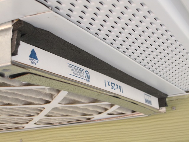
The solar heating system will use a 2500-gallon water tank to store the heat collected from the Solar Heat Collectors. The tank is 8 feet in diameter and 7 feet high. We could get by with a smaller tank, but using a large tank like this will keep the operating temperature of the system lower which makes the collectors more efficient. It also gives us the potential to store heat over a longer period of time, with up to one million BTU of usable energy storage. That’s enough to heat the house for nearly a week, depending on the outside temperature, so it’s not nearly big enough to collect heat in the summer and use it in the winter but it’s enough to get us through a week of cold cloudy weather if it starts out at full temperature. This polyethylene tank is rated at 140 degrees F max, so the solar collection system will have controls to make sure the tank temperature stays below that limit. Click here for a discussion of how the solar heat storage system was designed.

September 21, 2009
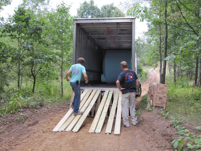
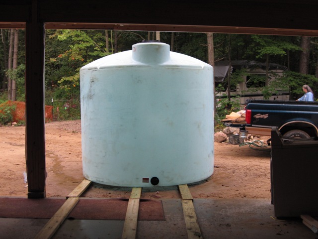
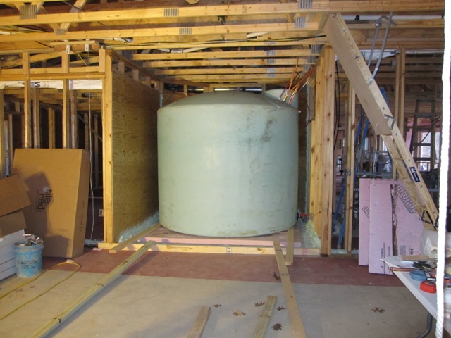
The big tank arrived inside a big truck. Our inspection revealed some small cracks along the bottom rim, so we initially refused delivery. After the vendor assured us that these are normal and won’t lead to tank failure, we reluctantly agreed to accept it. This is a commercial-duty tank that weighs about 450 pounds but it was fairly easy to roll it down planks out of the truck, and up the driveway to the garage. Standing it upright took a little more muscle but it was manageable with three of us.

October 29, 2009
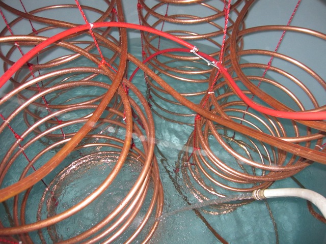
The water in the tank won’t flow anywhere; it just sits there in the tank absorbing and releasing heat. In order to heat the water in the tank using the solar collectors, and to later use that heat in order to warm domestic hot water and the floors, the tank has four heat exchangers in it. Each heat exchanger is a 100-foot-long coil of 3/4″ copper tubing inside the tank. Two coils are for the hot fluid coming from the solar heat collectors, which warms the water in the tank when the sun is shining. One coil is for domestic hot water, and it warms up the water coming from the well to provide hot water for fixtures in the house. The the fourth coil warms the water that flows through the tubing in the heated floor slabs.

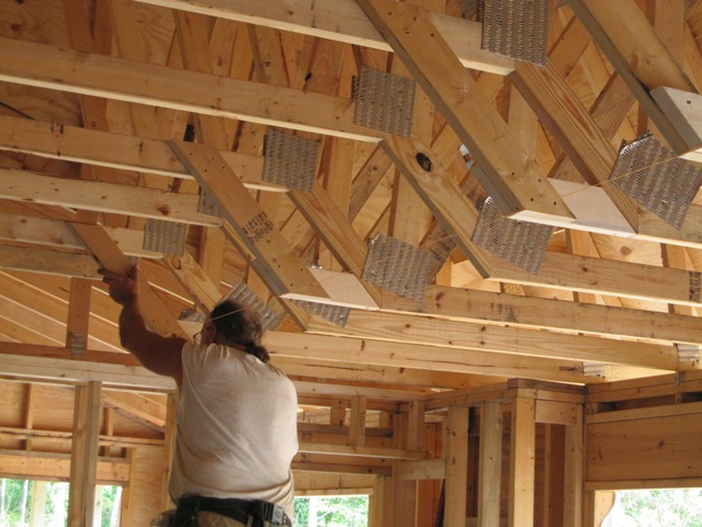
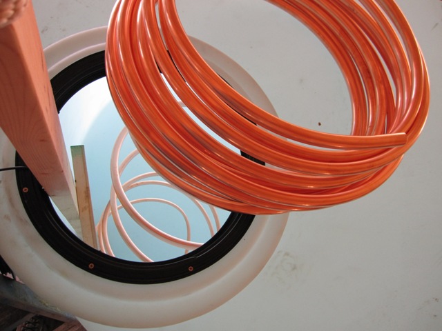
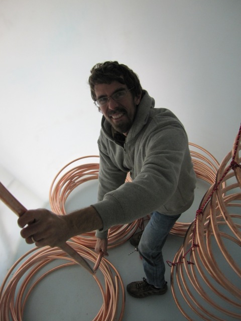
There is a 16-inch diameter hatch in the top of the tank, through which a slim person can just fit. In order to make the heat exchangers, we spiraled the copper tubing coils down through the hatch one at a time. It was a two-person job, with person one atop the tank feeding the tubing in and the other person inside the tank coiling it up on the floor.

November 1, 2009
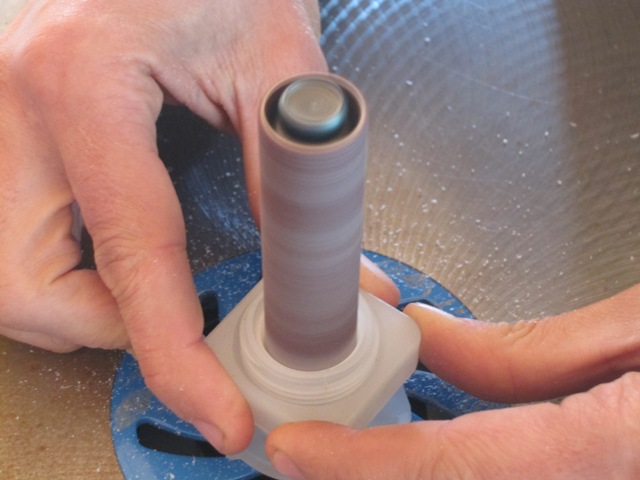
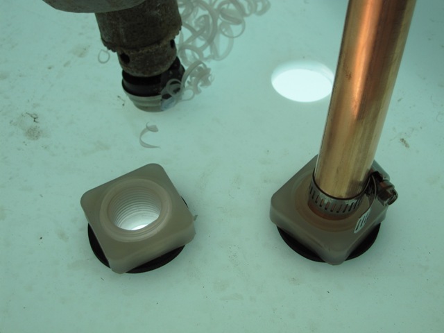
With four heat exchanger coils, we needed eight openings for the ends to pass through the top of the tank. Because the fluid coming from the solar collectors can get quite hot, up to 180 degrees F, we used polypropylene bulkhead fittings from U.S. Plastic Corp. to insulate the tubes from direct contact with the tank wall. The polyethylene tank is only rated up to 140 degrees F, while the polypropylene fittings can take up to 200 degrees. In order to fit the 3/4″ tubing through the fittings, they were enlarged slightly with an oscillating spindle sander. Then holes were drilled through the top of the tank with a large step drill and the fittings were installed. Hose clamps prevent the end of the copper tubing from slipping back in. Later we’ll seal the connection with silicone caulk. These are above the water line so they won’t leak water, but we don’t want any water vapor escaping into the cellulose insulation that will cover the tank.

November 6, 2009
Once the coils were inside, each was pulled up vertically like a spring and supported on polypropylene ropes suspended from the tank roof. In order to avoid leaks there are no copper connections inside the tank, only continuous lengths of copper tubing. The first photo below shows the first heat exchanger Jay made. The shape is a bit “artistic” but it should work just fine. Jay spent a lot of time down in the tank bending all the coils and tying them into place.

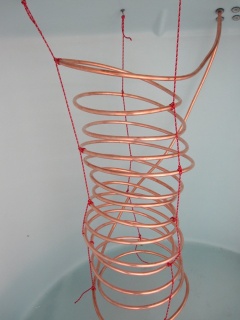
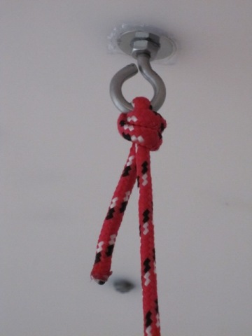
The first photo below is a close-up of a rope support at the top of the tank. All the hardware is stainless steel to prevent corrosion, and it’s sealed with silicone caulk to prevent any release of water vapor. The second photo shows how the ropes are tied on to the copper coils.

It did not seem necessary to knot the rope around every turn of the coil because the copper is fairly stiff, so the ropes were tied on approximately every third turn of the coil and this seemed to support it well. But in places where a rope might rub on the copper, a nylon cable tie was used to secure it so that it won’t wear down the copper over time.

November 8, 2009
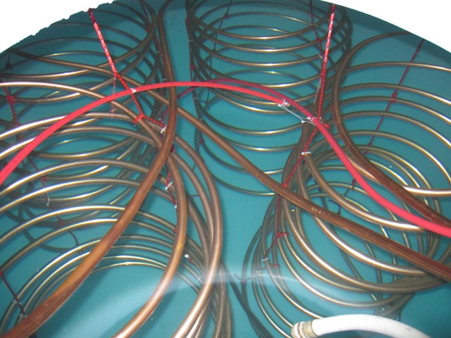
All four coils are now in place. In the first photo below, which was taken looking down through the hatch, the coils at the upper right and lower left will be for the solar collector loop that heats the tank. We’ll run the fluid through both of these coils in parallel, to provide double the surface area and increased flow rate compared to using just a single coil. The coil in the upper left is for domestic hot water, and the one in the lower right is for heating the floors. The coils are positioned such that no loop touches another, so that any movement caused by changing water flow won’t cause any abrasion of the tubes. The second photo, taken from inside the tank, shows the tubes passing up through the fittings in the top.

November 13, 2009
The device that controls the pump to circulate the fluid through the solar collectors needs to sense the temperature at the top and bottom of the tank, so that it only circulates fluid when the collectors are warmer than the tank water. The temperature sensors will be inserted into PEX tubes that are positioned as shown. The first photo shows the sensor tube at the top of the tank, ending about 8 inches below the top of the water. The second photo shows the tube running to the bottom of the tank, ending about 6 inches above the bottom. Because the sensors are not waterproof. the ends of the tube are sealed with watertight plugs.

November 15, 2009
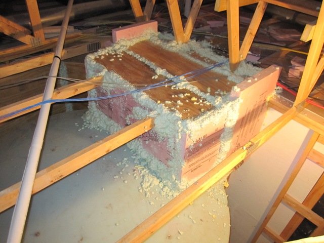
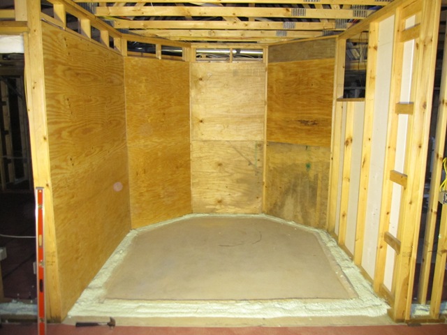
The tank will sit in a compartment at the back of the garage, between the garage and the main house. Inside the house these walls will be covered with drywall, and in order to prevent drywall cracking from temperature fluctuations or any possible moisture problems, we put plywood on the inside of the tank compartment. The concrete floor slab on which the tank sits is isolated from the main floor with foam insulation, so any settling won’t affect the floor of the main house and it won’t conduct heat directly into the main floor. That will be important in the summer! Although there’s already 6 inches of foam under this slab, We put an extra 3 inches on top to further reduce heat flow down into the ground.

November 16, 2009
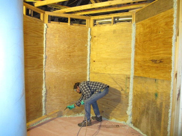
We used spray foam to seal the seams of the plywood walls and around the base. This probably wasn’t necessary but we had some spray foam left over and this seemed like a good place to use it up.

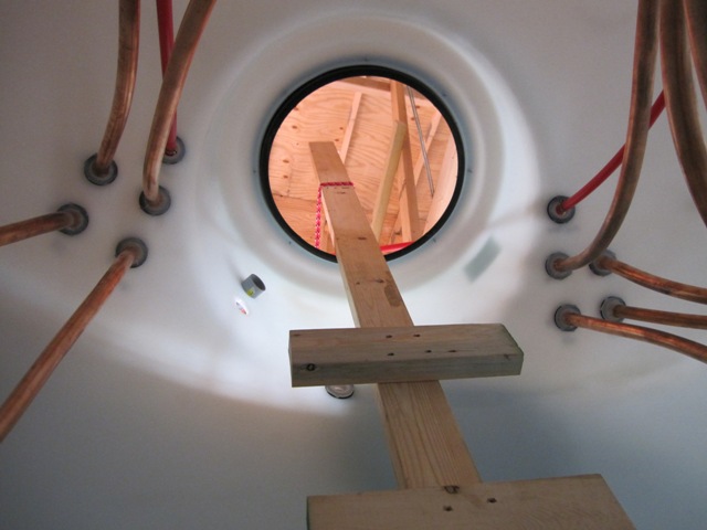
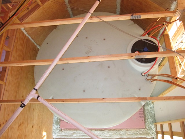
With the compartment prepared, we pushed the tank into place by sliding it on 2x4s. The tank itself weighs about 450 pounds plus about 200 pounds of copper tubing, and it was possible for two people to push it along the 2x4s. The second photo shows the view from up in the attic, looking down through the trusses. This compartment will be walled off from the garage and filled with cellulose insulation.

November 18, 2009
We filled the tank using a garden hose. Our well produces about 10 gallons per minute so it took about 4 hours to fill it. The total capacity is 2500 gallons but we can’t fill it right to the top so it actually holds about 2300 gallons. Including the tank and the copper tubing, that’s about 19,000 pounds of thermal mass! Both of these photos were taken looking down through the hatch.

November 19, 2009
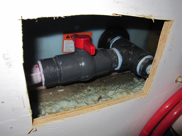
Here’s a photo of the drain valve at the bottom of the tank. This is an emergency drain, which can dump the tank water into the garage (where it will run out the garage door) in the event that we need to drain the tank in a hurry. This valve will be accessible through this opening from the mechanical room. A plywood box surrounds this area in order to exclude the cellulose insulation, and we’ll stuff it with fiberglass so we can get to the valve if needed.


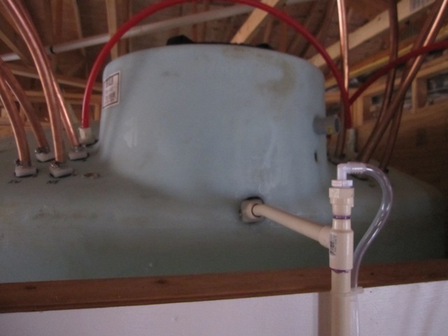
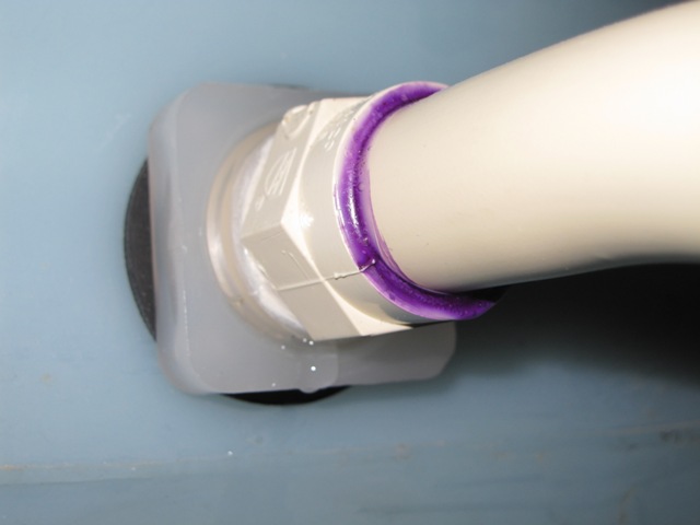
After filling the tank last night, we checked very carefully for leakage at these fittings. The fittings on the drain valve were just fine, but alas there was a minor leak up above. The first photo below shows the overflow pipe, which makes sure that the water level never gets as high as any of the other fittings at the top and also allows the tank to “breathe” as it changes temperature. The clear tube is a water level indicator, which comes from the fitting shown above. The second photo shows the leak. It’s actually leaking where the CPVC fitting threads into the bulkhead, and also around the rubber gasket of the bulkhead fitting. We’ll need to correct this, as water leakage would be bad once this compartment is filled with cellulose insulation.

November 19, 2009
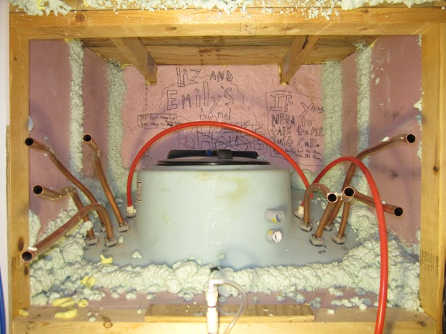
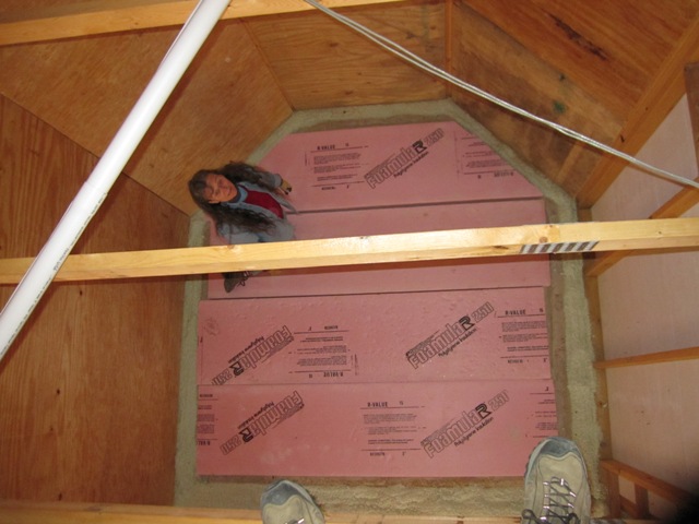
All the fittings and the hatch will be sealed soon, but there’s still a possibility of water vapor escaping through a leaky fitting and it would be bad if it were to permeate into the cellulose insulation around the tank. We want this area to breathe, so that any escaping water vapor can dissipate. After bending all of the 3/4″ copper tubing out into the mechanical room, we built a plywood and foam box around the hatch and fitting area in order to keep the out the cellulose insulation when it’s installed. The plywood on top rests on the trusses to provide overhead support, and the sides are made from 3″ foam board all glued together and sealed with spray foam. Our grand-niece Emily decorated the back piece before it was installed. After all the plumbing connections are made we’ll fill this space with fiberglass batt insulation, which will allow water vapor to exit if needed. The fiberglass can be removed easily if we need to access the fittings or hatch for any reason, without disturbing the cellulose.

The Solar Roof

September 19, 2009
We designed the south roof of the house to hold photovoltaic panels to produce solar electricity. Conventional wisdom says that the angle of the roof should equal our latitude (43 degrees) in order to maximize annual energy production. But conventional wisdom doesn’t clear snow from our roof, and neither will we! Our solar roof is oriented at a steeper 60-degree angle, in order to shed snow more readily and also to increase the length of the north roof slope that is our rainwater harvesting surface. According to PV-WATTS the steeper angle would reduce our annual energy production by about 8%, but this will be mitigated by less soiling and increased snow shedding in the winter. We still expect slightly less annual production than a 43-degree slope would give, but probably only by a few percent.

We came up with an arrangement of 30 Evergreen Solar panels rated at 205 watts each, for a nominal capacity of 6150 watts. Unfortunately the original manufacturer of our PV panels, Evergreen Solar, went out of business a few years after we built the house. Their former web site evergreensolar.com is now the home of the National Council for Solar Growth, a non-profit resource for solar energy information.

Originally the roof was going to look something like this:

Here’s how the south face of the house looks now:

Notice anything wrong? There are two problems, actually. First of all, the roof is lopsided! The framers built a 2-foot overhang on the right hand side when the plan called for a 1-foot overhang, so the roof is actually 1 foot longer on the right (east) half. Oops. It doesn’t look bad now but it’s going to look strangely lopsided with a nice symmetrical pattern of solar panels on it. The second problem is more subtle but more worrisome. On the lower left corner we added a small porch roof, and we kept it as low as practical but it still comes up a bit higher than the bottom of the lowest solar panel would. In the afternoon it will shade a small corner of that panel, which is more serious than it might sound. The panels are connected in series, and the cells within each panel are connected in series, like Christmas lights. Shading even a small portion of one panel is almost like removing a bulb from a string of lights and it will significantly reduce power from the entire string, or half of the array in our case. We’re not as worried about the tree shadows on the roof, as this photo was taken early in the morning while the sun was still low.

September 22, 2009
Fortunately we came up with a simple solution to both problems. We had the carpenters add a foot to the left half of the roof, so now it’s symmetrical except for the little bite taken out of the lower left corner by the porch roof:

And now that this roof is 2 feet wider than originally planned, we designed a new arrangement for the 30 panels that avoids the shading in the lower-left corner. We like the appearance better too.

As long as they were modifying this roof, the carpenters also closed in the overhangs on the east and west sides in order to eliminates places where snow could accumulate. It was Dan’s idea and we like it a lot better this way. These photos show the 1-foot extension being added, and how it looks afterward.

They did the same thing on the east, eliminating a likely area of water infiltration and saving a little bit of roofing. So due to the mistake by the framers, we now have a better arrangement of solar panels and less chance of water intrusion. Serendipity happens.

Theater

September 10, 2009
The living room in the main house doubles as a home theater, and the east wall is designed to serve as a projection screen with a projected image about 8 feet wide. In the first photo below, we set up a piece of white plywood to test the screen location. We decided that the bump-up ceiling tray was a little too wide so we had the carpenters bring it in a foot on the right hand side. This gives us a comfortable 2 feet on each side for the speakers.


September 28, 2009
Here are the Polk Audio speaker enclosures mounted in the screen wall. These will provide an acoustic enclosure for each of the main right & left speakers. The center channel speaker will sit just above the screen in the angled wall of the ceiling tray.

Recycling

September 9, 2009
We found a local company Cannonsburg Wood Products that accepts all types of wood waste for recycling, including plywood scraps and even pieces with nails. Liz loaded up the trailer full of small scraps from construction and delivered it to them to be ground up into mulch. Some of the pieces look pretty good in this photo but most are smaller than the ones on top and many of them contain nails, staples, etc. We assume they remove all the metal with magnets, and the mulch they sell looks pretty good.

December 3, 2009
The drywall is nearly complete, and all of the board has been hung on the walls and ceilings throughout the house. Here’s a photo of the scraps, loaded into a 30-yard container fromPhoenix Resources. The container is roughly half full so we have about 15 cubic yards of drywall scraps. These will be ground up and recycled as a soil amendment.

Electrical

September 9, 2009
At last the Consumers Energy crew arrived to run the underground electrical service. They started by the pole in the neighbors’ yard, using this Ditch Witch to dig a trench about 3 feet deep as they laid the cable. This is a high-voltage cable that will run to a transformer near our house.

September 10, 2009
Installation continued as they ran the low-voltage (240 volt) cable from the service entrance near the garage out to the transformer by the driveway. On the left you can see the generator that we’ve been using during construction. We’re really looking forward to not needing it anymore!

September 11, 2009
Today the transformer was installed and the service hooked up. If you’ve ever wondered what those big green boxes look like inside, here’s an inside view. Only about 1/3 of it is the transformer, with the other 2/3 empty space for the big wires and connectors. This transformer is big enough for several houses but it’s the smallest size that they have. The primary cable coming in on the left carries 4800 volts, and the secondary wires on the right carry 240 volts going to the house.

Floor Finishing

September 5, 2009
We purchased a sample kit of acid stains for concrete from Direct Colors. The kit includes 4-ounce bottles of the 10 stain colors that they offer. These stains are designed to react chemically with concrete to produce a variety of colors, mostly blues and browns. We cleaned a 30-inch wide area of the cottage floor that will eventually by covered by a cabinet, and applied each stain in a 3-inch-wide strip. Each strip is further divided in half, with the left half getting the stain full-strength and the right half getting the stain diluted 50% with water. The second photo below shows how it looked right after we applied the stain.


The first photo below shows the stain appearance after it had dried, and the second photo shows how it looks after thorough cleaning.

Some of the colors aren’t bad, but they aren’t exactly great either. And these stains pose some hazard in application due to the hydrochloric acid they contain, as well as for clean-up since some of them contain copper and chromium. A small area like this isn’t much of a hazard but spreading these nasty chemicals over thousands of square feet does not appeal to us! Fortunately we found an alternative called SoyCrete, a non-hazardous soy-based stain for concrete. We’ve ordered some samples, and we’ll do a similar test once they arrive.

September 17, 2009
Liz applied the SoyCrete stain samples in an area near the first test. The colors in the photo below are not directly comparable to the acid stain photo above because the lighting is different, and the ones above were still a bit wet whereas these are dry. In general the colors are not bad, but not great either. We suspect that part of the problem is that the concrete was troweled a lot, which closes up the pores of the concrete and makes it less receptive to stain. We’re going to try etching the concrete with citric acid, i.e. lemon juice, which is a lot less toxic than the hydrochloric or phosphoric acid used in most concrete etch products. Then we’ll do some more stain tests to see if the etching makes a significant difference.

January 21, 2010
We finally settled on the SoyCrete stain, and chose the color ‘Augusta Green’ for all the floors in the house. Our nephew Nash did the hard work of scrubbing and washing all the floors with SimpleGreen general-purpose cleaner. Once they were clean, he applied Eco-Etch etching solution, which is a relatively nontoxic and nonhazardous etcher and cleaner also made by Ecoprocote and recommended for use with the SoyCrete stain. He applied one coat of etch using a paint applicator pad, and then a second coat after about 15 minutes. Then he washed it off with more SimpleGreen and rinsed it clean. This process leaves the concrete very clean with open pores that will absorb the stain better.

Initially we had Nash apply the stain using a sponge mop, which worked pretty well but it did leave some lap marks. Eventually he switched to sponging it on by hand, which gives a more even coverage.

Here’s a photo showing one of the bedrooms shortly after the stain was applied. The stain is still a bit wet in this photo, but it will look similar to this once it has dried and has been sealed with sealer. The color will deepen somewhat after the sealer has been applied. The patterns in the floor come mostly from the varying surface texture and color of the concrete, and it looks rather like jade.

January 26, 2010
After cleaning and etching the floors in the main living space, Nash applied the floor stain. He used a new sponge applicator that spread the stain well, but it left a lot of streaks that didn’t look so good. After some experimentation we found that the best technique was to spread the stain, wait a few minutes for it to mostly dry, and then buff it with a damp sponge to even out the brush marks. It was hard work but it gave the best finish of any technique we’ve tried.

The first photo below shows Nash applying the stain as Liz buffs it out. The second photo shows the stained floor of the studio, with the living room beyond. The swirl patterns you can see in the second photo are not from unevenness in the stain application. They are due to surface irregularities made by the power trowel that was used to finish the concrete slabs.

We even found some shoe prints in the concrete, right in the living room! They were not visible until we applied the stain. This is just part of the character of stained concrete floors.

January 27, 2010
Liz and Nash sealed all the floors in the main house today. Liz sprayed on the AcriSoy sealer using a pump-up garden sprayer, and then Nash rolled it out with a paint roller. They applied just enough to wet the surface evenly so there was no puddling. The sealer absorbed into the concrete and was dry to the touch in about 15 minutes. After about an hour they applied a second coat.

Here’s the final result. It’s a bit less green than we expected, since the hard-troweled areas did not absorb much stain and remained relatively gray, but we like the effect.

January 30, 2010
Liz and Bruce finished up the staining of the entryway floor. The first photo is looking south with the cottage great room behind, and the second shows the entryway looking west toward the front door. The light green rectangle on the left is a temporary spacer where the metal doormat will go.

January 31, 2010
Here’s the finished floor of the cottage looking north, with a little bit of the entryway floor beyond. Overall the floors look pretty uniform in color throughout the house, and the color variations in these photos are mainly due to different lighting at different times of the day.