Includes affiliate links that help offset our expenses at no cost to you.
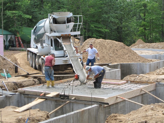
June 25, 2009
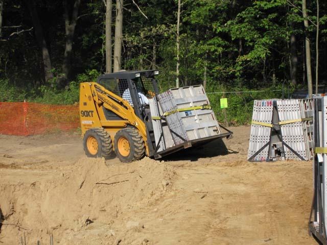
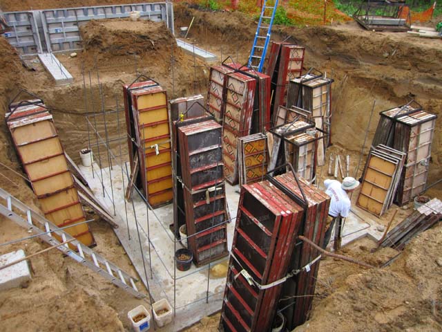
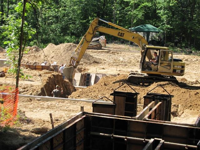
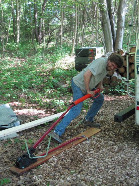
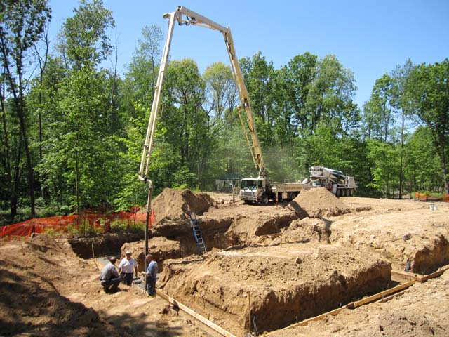
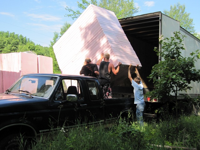
Today the semi truck arrived from Insulation Depot carrying about 10,000 square feet of 3-inch-thick extruded polystyrene foam. It is reclaimed foam that was removed from service, possibly from a cold-storage warehouse. The sheets are 2 feet wide and 8 feet long, and they came bundled in 11 pallets of 60 sheets. Each pallet weighs a few hundred pounds. After pondering how we would get them out of the semi trailer, we decided to drag each one onto the bed of the pickup truck, then dump it off to the side. Thanks to help from Jack, Di and Nash we were able to get them all unloaded in about an hour.


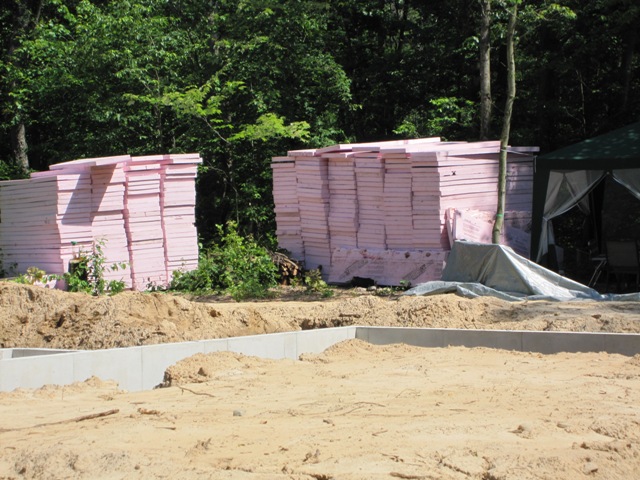
Liz spent the rest of the day carrying foam sheets up to the building site. She moved 660 pieces of it! This photo doesn’t quite show it all.
June 29, 2009
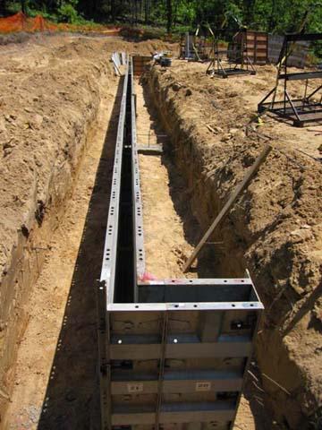
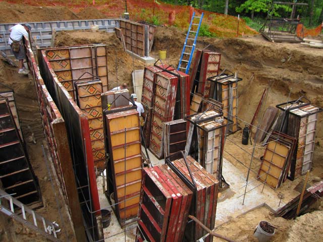
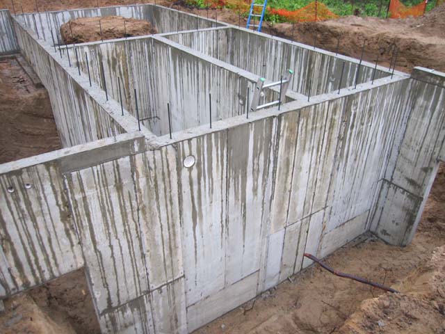
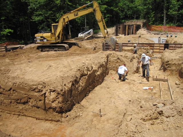
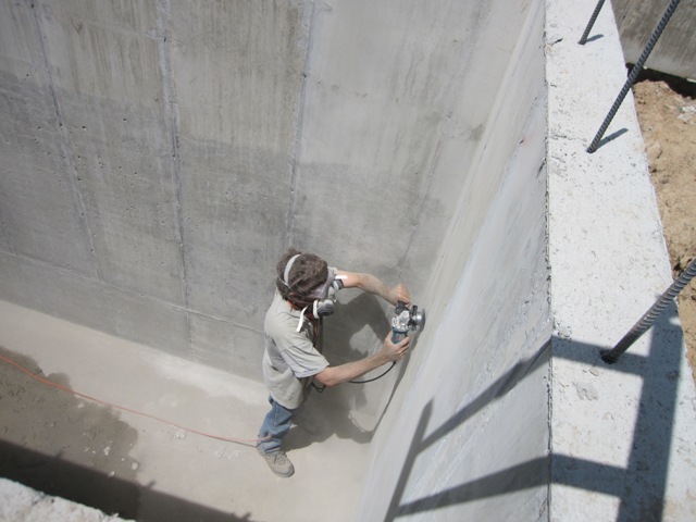
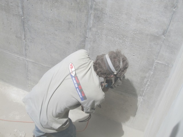
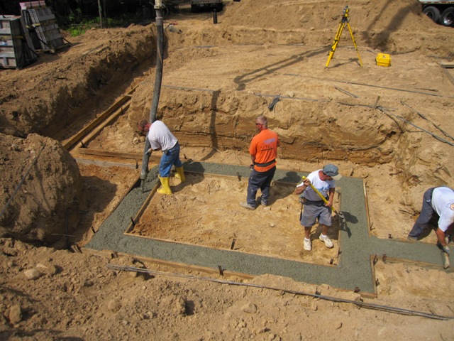
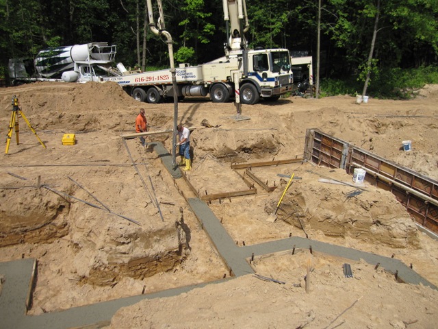
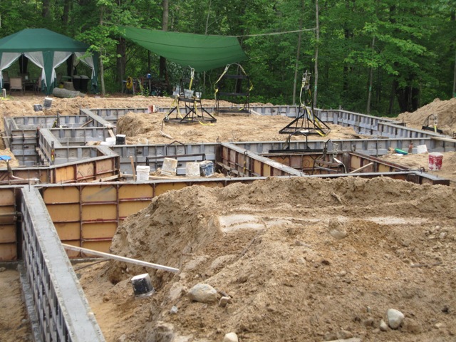
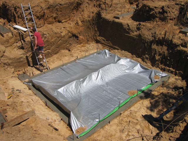
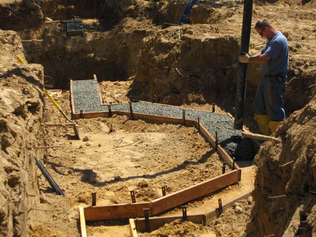
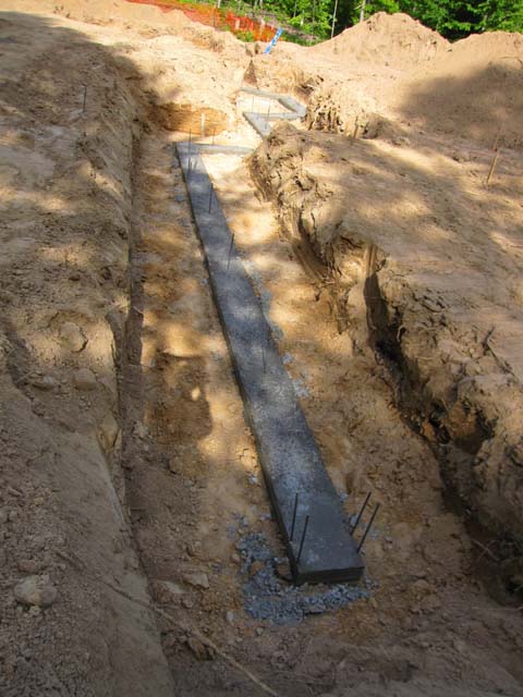
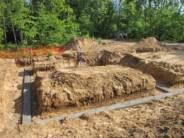
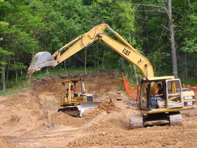
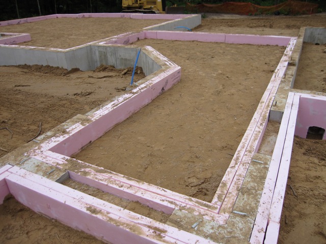
Today the excavators started back-filling inside the cottage.Once they had the grade about right, we placed foam sheets vertically inside the foundation walls, making two layers 24″ high and a total of 6″ thick for an insulation value of R-30. This will greatly reduce heat loss at the edges of the heated slab.

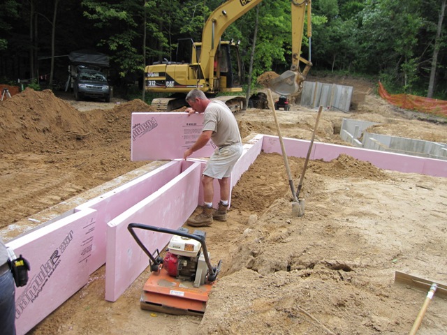
After each section was cut and fit, they compacted the soil around the foam.

The corner joints are staggered to provide better coverage, in order to prevent thermal bridging from the warm slab to the cold foundation walls. Once the foam was all in place they dumped in more sand to bring it up to 10″ below the tops of the walls, and kept compacting it so it won’t settle under the slab. After the under-slab plumbing is in place this will be covered with a moisture barrier, 6″ of foam and then 4″ of concrete to bring the finished floor level up to the level of the foundation walls.


June 30, 2009
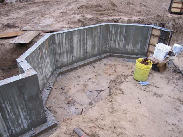
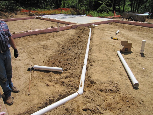
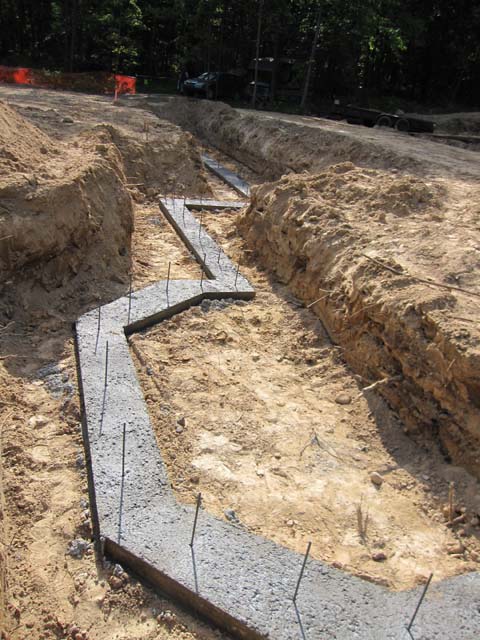
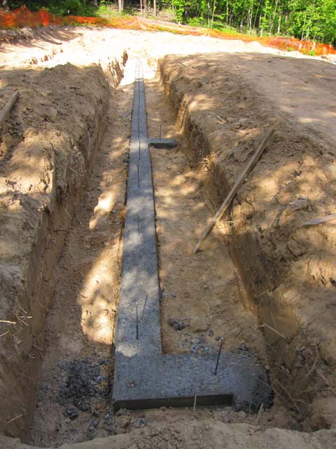
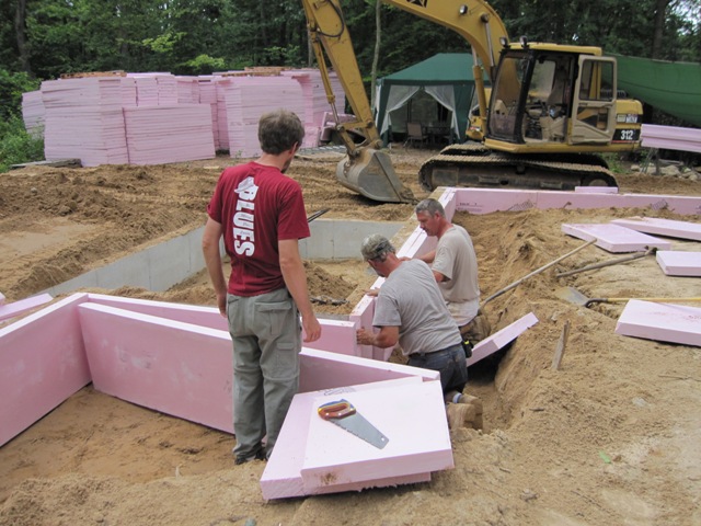
Back-filling continued through the front porch and entryway. We cut holes in the foam for pipes that will run through the foundation walls and under the slab.


The foam was beveled to fit around the 45-degree corners in the entryway and the dining room.


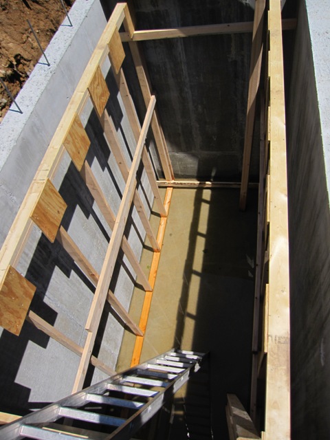
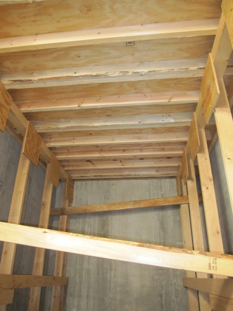
The first photo below shows the entryway looking west from inside the house, with the cottage beyond to the left and just a bit of the garage showing on the right. The second photo shows the front porch looking east as you approach the front door, with the entryway and main house beyond, garage to the left, and cottage to the right.

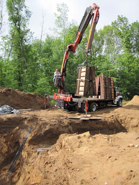
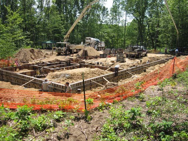
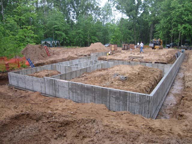
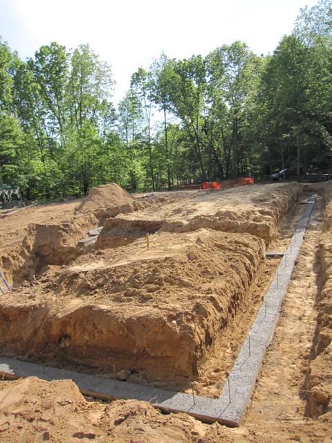
With the entryway done, the excavator moved in to start back filling the main house.

July 1, 2009
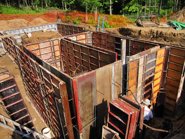
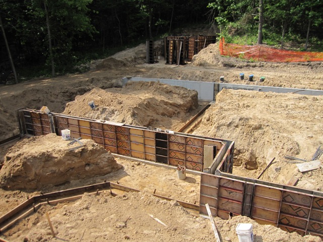
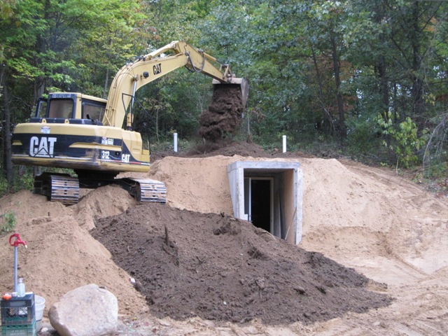
Today started with more back filling, inside the house and workshop and around the cistern.


The walls were back filled inside and out at about the same rate, and compacted every 12″ inside.

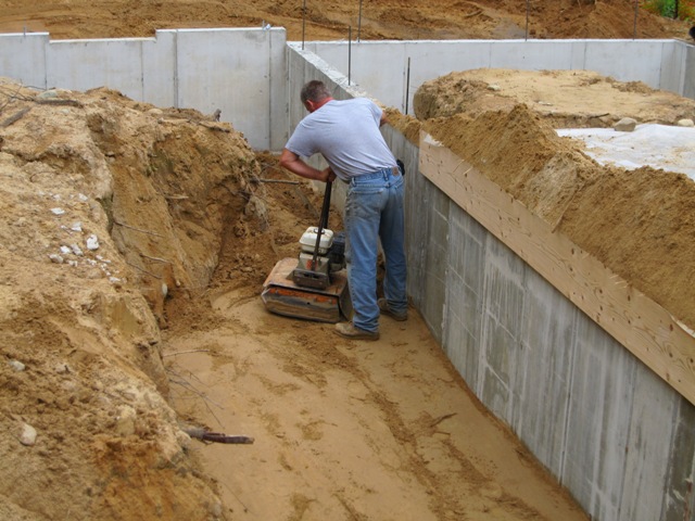
Once the dirt was up to 24″ below the walls, we added the foam on the inside of the main house and in the workshop. The workshop won’t be heated like the house, but we still want the slab well-insulated so it gets the same level of insulation as the house slabs. The shop will have large clerestory windows on the south and reasonably good insulation in the walls so it should maintain a comfortable temperature most of the time just from passive solar gain. Then we can warm it up when needed with a wood stove.


July 9, 2009
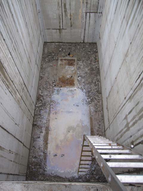
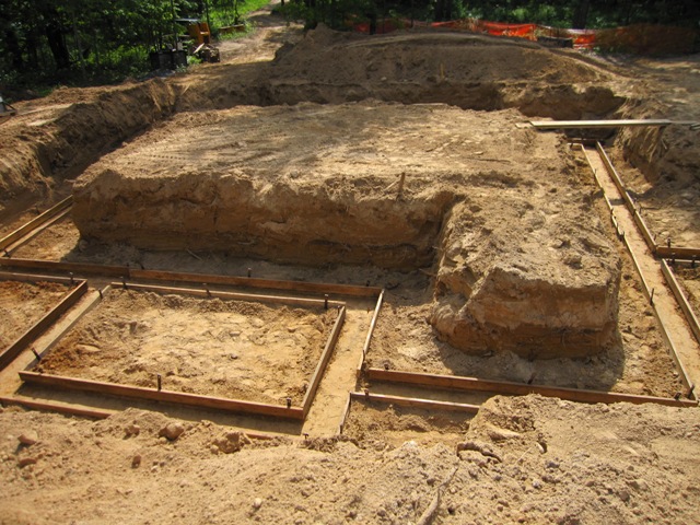
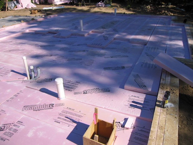
We used a Water Levelto level the dirt inside the cottage to about 10″ below the top of the foundation walls. That allows for two layers of 3-inch foam plus 4 inches of concrete. Once it was all level (a tiring job!) we laid the first layer of 3-inch foam over the dirt.


In order to cut the foam accurately we set up a nichrome wire powered by our 75-watt solar panel, to melt through the foam in order to cut straight lines and round cut-outs for the pipes. It worked great, except when the sun was covered by a cloud. It was partly sunny so we found ourselves watching the sky to guess when we’d get a few minutes of cutting in between clouds. The next day was mostly cloudy so we had to switch to a transformer powered by a generator. The solar panel was quiet and more fun but the generator was more reliable.


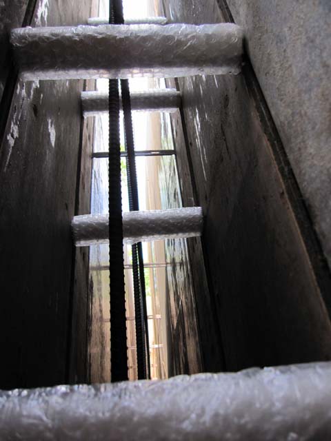
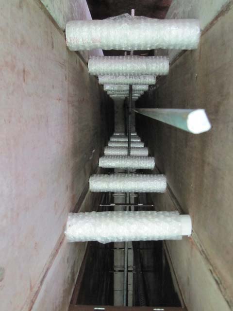
We laid down 12-inch-wide pieces of foam under the hot water conduits and flush with the dirt, and then we ran the first layer of foam up over it and against the conduit. With the second layer of foam over it all, the hot water conduits will be insulated with 3 inches of foam (R-15) on all sides. Later we’ll push 3/8″ PEX tubing through these for the hot water runs to the fixtures.


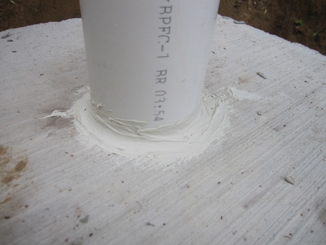
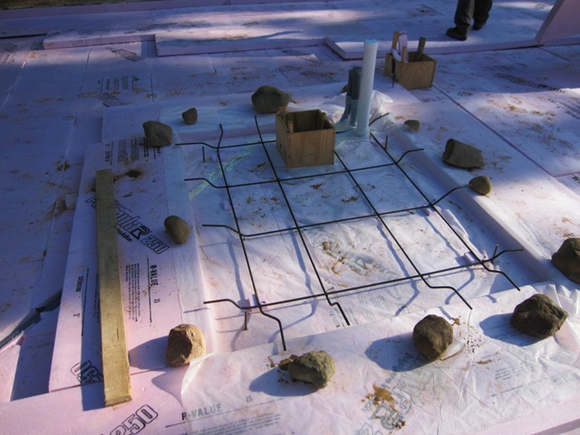
In the photos above and the one below, you can see a small reddish tube that we placed under the foam. This tube is about 10 feet long and ends in a solid plug as shown below. Later we’ll push a temperature probe down through this tube, in order to let us monitor the temperature of the dirt right under the foam. A similar tube is placed right above it on top of the foam and at the bottom of the concrete slab. By measuring the temperatures of the slab and the dirt below it, we will be able to determine how much heat we are losing through the foam. That won’t help us directly, but it will help answer the question of whether 6 inches of foam is too much, too little, or just right.

After the first layer was done, we laid the second layer with the 2’x8′ sheets running in the opposite direction to give us 6 inches of foam total. With three of us working we were able to lay all the horizontal insulation for the cottage in a day, including the time it took to make the solar foam cutter.

July 14, 2009
The insulation under the workshop was laid in two layers much like that in the cottage.


With the shop insulation in place, we started leveling the dirt in the main house. Here you can see the hot water conduits running to the bathrooms on the left and the kitchen on the right, with insulation underneath them at dirt level.

July 17, 2009
The main house required a lot of foam, which Peggy and Liz carried up to the foundation as the others laid it into place.

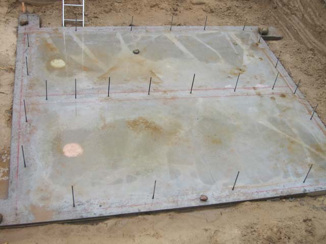
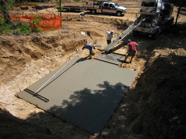
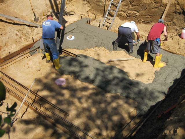
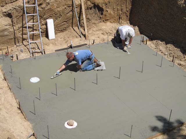
In the photos below you can see the first layer of foam in the house, and the area around the shower base. In this area we put only one layer of foam so it’s 3″ lower than the main slab. This will let us build a roll-in shower that sits just slightly lower than the bathroom floor.

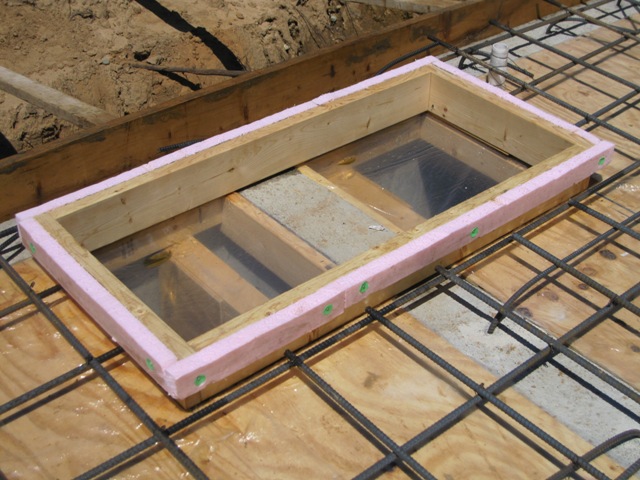
Here you can see the shower base poured full of concrete 4 inches thick, as the rest of the second layer of foam is laid into place. We built a curb around the area that will hold the 2500 gallon water tank, which will store heat from the solar heat collectors. This serves two purposes. It insulates this little slab from the main slab so that the heat won’t leak out when we don’t want it to. And it allows this slab, which holds 20,000 pounds of water, to settle independently of the main floor slab without cracking it. Although that’s a lot of weight, it’s spread out over a large area so the pressure on the foam will be less than the pressure created by a person standing on one foot. We expect it to settle a little, but not much.