Raw Materials
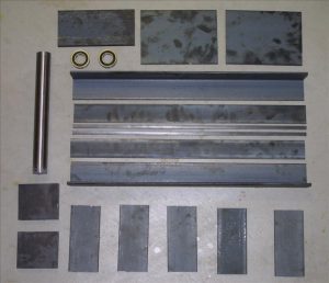
I ordered most of the steel I needed from Metal Express and they have a branch nearby so I avoided shipping charges. I ordered the 2” ball bearings and the1.5” drill rod that I used for the lathe spindle from Enco. Here’s a picture of the steel plates and angles, plus the bearings and the drill rod for the spindle.
Preparing the Pillow Blocks
Because the steel was rough-cut I needed to flatten the bottoms of the pillow blocks, and then drill and tap them for 3/16” bolts. I drilled a couple of holes in them in order to mount them to the top slide of the metal lathe. This was an easy and solid way to mount them, although it made it harder to bore the bearing holes later. I squared them as best I could to the headstock to minimize how much I’d have to cut.

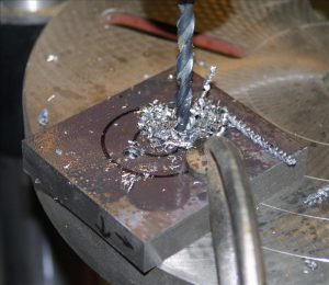
I used a fly cutter to flatten the bottom face of each block so it would sit solidly and squarely on the headstock.

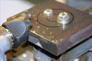
I drilled and tapped holes in the bottoms for 3/16 bolts to hold them to the headstock.
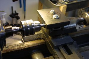

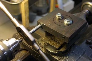
I drilled 4 bolt holes in the top plate of the headstock in order to attach the pillow blocks. I drilled them a bit oversize (7/16”) so I’d have some room to slide the pillow blocks around in order to align them.
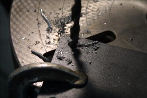
Welding the Bed
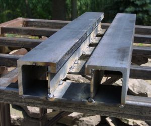
I started welding the bed by attaching the 3/8” square clamping strips to the 2” angle. These strips make the top of the bed the same thickness (5/8”) as the bed on my Jet lathe so that I can interchange the tool rest and tailstock between the two lathes without having to adjust the clamps. They don’t have to take any force and the inner surface will have to be ground smooth so I just tack welded them in several places. In the photos below, the angle is on its side so that what will become the top surface of the bed is to the right.
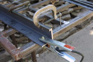
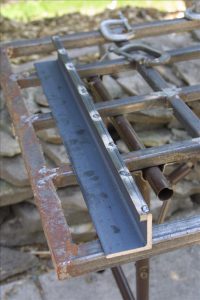
Then I welded on the 1/8” support strip that goes between the top of the bed and the cross plates on the bottom. In the photos below the piece is upside-down so the top surface of the bed is on the bottom. First I tack welded it on the inside just to hold it in place, then I went back and welded a continuous seam all the way down (the third photo shows it welded partway).
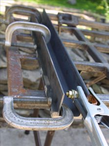
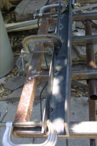
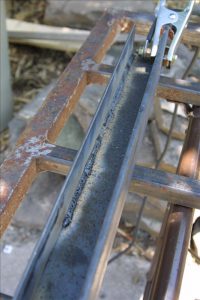
The inner surface of the ways must be ground flat so that the tool rest and tailstock can slide along it. I ground it approximately flat at this stage, but more grinding will be needed later to get the spacing just right.

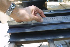
After both halves of the bed were welded up, I laid them out with spacer blocks in between to get the spacing right. I made the spacer blocks just a little short, so that the gap between the halves was just a little too narrow for the tailstock to slide in. This way I can grind it afterward for a good fit. Then the bottom support plates are laid on and welded.

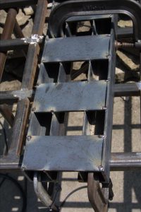
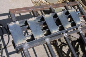
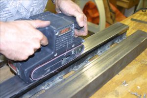
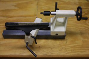
You can see below that the support strip on the left twisted a little so it’s not quite vertical – a cosmetic flaw but it won’t affect anything. By design, the gap is a little too narrow for the tailstock to slide in. I got a good sliding fit by carefully grinding the inside surface, checking often for straightness and the right gap. Then I sanded down the top surface of the ways, just enough to make them smooth (but not perfectly so). The tool rest and the tailstock fit reasonably well. I ended up with just a little side-to-side playin the tailstock, from grinding the insides of the ways a little more than necessary, but it won’t have much effect on the operation of the lathe.
Welding the Headstock
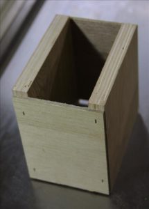
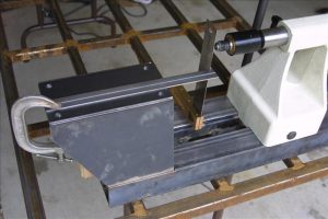
In order to position the top plate of the headstock correctly I made a wooden spacer box. With the top plate resting on this box I aligned the top plate using the tailstock so that it was accurately centered and lined up along the axis of the lathe. This is not a critical alignment because the bearing holes in the pillow blocks aren’t bored yet. I laid up the angled sides of the headstock and tack welded them together, then I removed the box and welded everything solidly. My welds aren’t very pretty, but at least they’re strong. I ground down the welds on the top plate so that the pillow blocks will sit solidly on the plate surface.
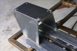
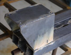
Marking the Pillow Blocks
I bolted the front pillow block to the top plate, positioning the bolts about in the middle of the oversize holes in the plate so I’ll have a little wiggle room in all directions. Using the tailstock I marked the center of the block and then precisely bored a ½” hole in it. I made an “arrow” out of ½” drill rod and turned it to a point at one end. This goes from the center in the tailstock, through the hole in the front pillow block to the rear pillow block. I marked where the point touched as the center of the rear bearing.


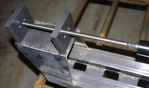
Boring the Pillow Blocks
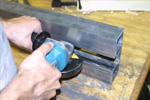
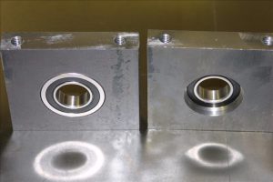
I bored out the 2” holes for the bearings, leaving a narrow shoulder against which each bearing will seat. It took a long time to bore them out, and the mounting holes I drilled earlier made it a bit rough until I had bored past them. I tried to get a close fit but loose enough for the bearings to slide just a tiny bit to help alleviate any axial misalignment of the blocks when mounted to the headstock so the spindle wouldn’t bind. The fourth picture below shows the blocks upside-down (with the bolt holes on the top); the one on the left shows the front side where the bearing slides in and the one on the right shows the back side where the bearing seats against the shoulder. I made sure the shoulder was narrow enough that I could drive a bearing out by tapping on the outer race.
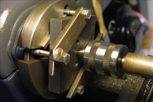


Making the Clamp
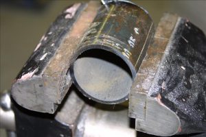
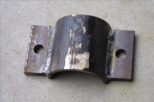
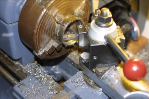
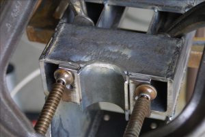
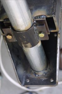
The headstock clamps on to a vertical support post, with the top of the post fitting into a tapered receiver under the top plate. I made the clamp from 2” black steel plumbing pipe, and the inside diameter is a bit too small to fit around the 2” conduit of the support post so I flattened it slightly before cutting it apart. The outer part of the clamp has two wings welded to it, with slightly oversized (7/16”) holes for the 3/8” bolts. I bored the receiver with a 3-degree taper so that it fit snugly around the conduit at its narrow (top) side.
Welding the Clamp
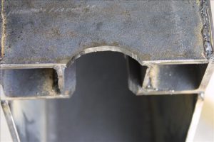
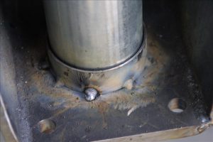
The plate on the bottom of the bed is notched to fit the clamp. I leveled the bed and then used a level to align the clamp and the receiver before welding them on. I just tack welded the receiver in several places to avoid distorting it too much. Beside the clamp on the back of the bed I welded two wings with 3/8” tapped holes for the bolts. In these photos the headstock is upside-down.


Making the Base Frame
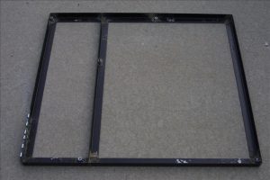
I welded up a frame for the base from some 1/8” thick, 1.5”wide steel angle I recycled from an old bed frame. This later turned out to be too flimsy so I ended up welding on ¼” plates to the outside. It would have worked better if I’d started with ¼” thick angle instead. The center brace of the frame will extend right beneath the posts that support the headstock and tail of the lathe. Onto the frame I welded 3/8” coupling nuts, which were 1.75”long cut in half to make nuts about ¾” long. These are welded at 5 points on the frame to make the attachments for the legs. I used loose-pin hinges for the motor mount, drilled out (very slightly) to accept a ¼” rod through both hinges. The hinges are welded onto the base frame where the motor will attach, with the hinge rod through both of them while welding to keep them aligned.

Making the Legs
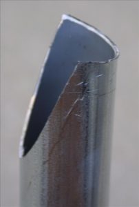
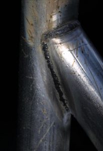
I made the legs from 2” thin-wall electrical conduit because it’s cheap (about $1/foot at Home Depot), reasonably lightweight, and quite stiff. In order to join the tubes I had to cope them, and I determined the profile using a wye joint calculator that I originally created for making Y branches in my dust collection ducts. I set the duct diameters to 2.2” and entered the angles I needed, and printed out the branch duct profile that I marked on the end of the tube. Then I just cut the profile with a saber saw. I got a pretty good fit, but I had to bend the “wings” out a little to account for the inner diameter of the branch tube mating to the outer diameter of the main tube. I welded the tubes to 3/8”thick by 2” wide steel plates at the bottom, through which I drilled the bolt holes for attaching to the base (I cut and drilled these plates and made sure they bolted to the base before cutting the tubes). While welding these tubes I made sure to avoid breathing any zinc fumes from the galvanized coating.


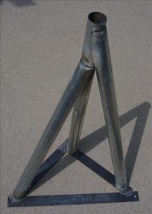
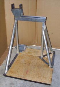
Making the Spindle
I made the spindle from a 12.5” long piece of 1.5” W-2 drill rod. I chose W-2 steel simply because I happened to have some, but I didn’t heat treat it in any way. First I squared off each end and drilled center holes so I could mount it between centers.
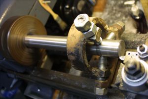
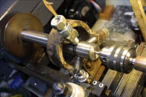
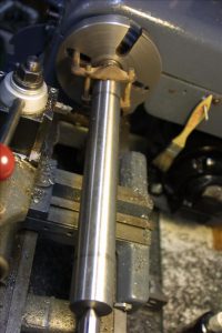
I cut a shoulder to mark the end of the main shaft, where the flange will seat against the front bearing. I turned the main shaft down to a little under 1” diameter in between the bearing areas, and then turned it to exactly 1” at the bearing points, using the bearings to check the fit often. I used some 320-grit wet/dry sandpaper to finish the surface for a nice snug fit in the bearings. I turned the end of the spindle down to ¾” to fit the sheave for the drive belt.


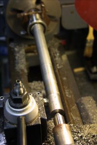
The spindle nose is threaded to match my Jet lathe so that I can use the same faceplate and chuck. Beyond the threads is a “locking groove” for the set screws of the faceplate or chuck, and I just turned this to match the dimensions of the Jet spindle. I cut the threads by angling the top slide to 30 degrees (half the 60-degree thread angle) and advancing the cut using the top slide rather than straight in using the cross slide. This is a technique I learned from The Amateur’s Lathe that puts a lot less stress on the lathe than feeding the threading tool straight in.

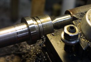

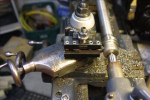
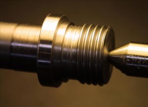
This completes the spindle. I did not bore it out for a Morse taper because I don’t need a drive center for bowl making. If I ever need a drive center I’ll make one that threads onto the spindle, which should be considerably simpler than drilling through the spindle and cutting an accurate inside Morse taper. Having a solid spindle also precludes using a vacuum chuck but if I ever want to use one I could still drill a small hole through the spindle.
Truing the Motor Pulley
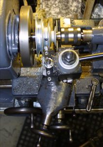
I bought a fairly cheap step pulley for the motor shaft and it was not very well made, with molding flash in the grooves and a poor finish. I put it on the lathe and trued it up by setting the top slide angle to match the groove angle (17 degrees) and taking a light cut across each face.
Aligning the Bearings
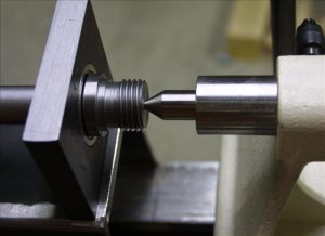
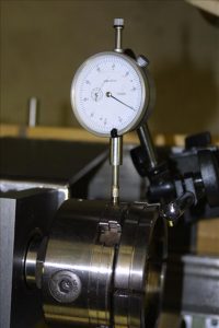
With the spindle mounted on the headstock I aligned the front bearing by centering the spindle on the tailstock center. To align the rear bearing I mounted a wooden dowel in the chuck and rotated it to determine the center of rotation out on the dowel end (which need not be in the center of the dowel). If everything is aligned correctly the center of rotation will meet the tailstock center, and I shifted the rear bearing side-to-side to align it horizontally. I expected that I would have to shim one or both pillow blocks to get things aligned vertically, but it came out extremely close without any shims. I found that the spindle rotation got a little tight when I tightened down the bolts, because the bottoms of the pillow blocks were not fly-cut exactly square to the faces. I expected this and figured I’d have to shim them a little to get them square. One thickness of aluminum foil under the rear edge of the front pillow block did the trick. I checked the spindle run out with a dial indicator on the edge of the chuck and it was only 0.001” worse than my Jet lathe. Not too bad for a first try, and plenty good enough for making wooden bowls!

Mounting the Motor
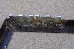
I bought a 1-HP motor at Fleet Farm, and spent a bit extra for a ball-bearing motor so that the belt tension won’t prematurely wear out the bearings. I mounted the it to a 11”x14” piece of plywood and attached the hinges at the back. I wired in a power switch and a reversing switch so I can reverse the motor while sanding. I found a decent and reasonably cheap 20-amp power switch at Woodcraft, and removed the outlet so I had a place to mount the reversing switch. I welded some tabs on the rear lathe support leg so I can just hook the switch box to the leg and remove it easily for transport.
Making Bowls!
I set up for a first test in the garage, and turned a 10”bowl out of catalpa. It’s a fairly low-density wood so this was not a severe test of vibration, but I found that the lathe vibrated quite a bit until I got the blank trued up. After that it wasn’t too bad and I was able to turn a decent bowl. I moved the lathe out into the yard to see whether it would be less vibration-prone when sitting on grass instead of concrete (where the uneven surface means the base doesn’t make contact all the way across). It was a bit better on grass and I turned a larger 12” bowl, which came out pretty good. There was still quite noticeable vibration when the blank was rough and not balanced, and it seemed that part of the problem was that the base was too flexible so I welded ¼” thick by 1.5” wide steel all around the outer edge and across the center brace of the base frame to stiffen it.

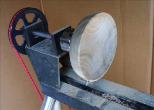

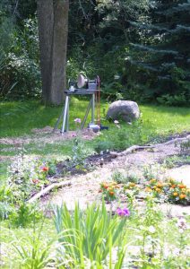
I also found that the belt slipped when rough-turning the blank at the low speed (with the smallest pulley). The weight of the motor just wasn’t enough to hold sufficient belt tension so I added a clamp to the support leg that will hold the motor board down and provide enough tension on the belt.
Painting
Once I was satisfied that I wasn’t going to be altering the base or the lathe body, I primed all bare metal on the base frame and the lathe body using a metal primer and then painted them with two coats of a rust-inhibiting spray enamel. First I removed the spindle and bearings and masked off the inner surfaces of the pillow blocks with high-quality masking tape. I also masked off the top surfaces of the lathe bed.