December 14, 2009
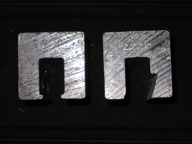
We purchased S-5! clamps from Affordable Solar in order to mount the solar panels onto the standing-seam metal roof. These clamps are designed to grip the roof seam using set screws and they work with a wide variety of roofing profiles. Unfortunately the clamps weren’t compatible with the rib profile on our roofing so we had to modify them. After a few experiments we determined that a 20-degree bevel on the right-hand side would grip under the fold of the roof seam, and that we needed to enlarge the left-hand side slightly in order for the clamps to seat properly. Dan modified the aluminum clamps by bolting each one to a piece of wood and then running it over his table saw in 3 passes. The second photo below shows the profile of the clamp before and after modification.

December 15, 2009
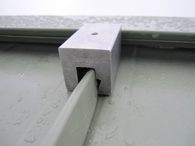
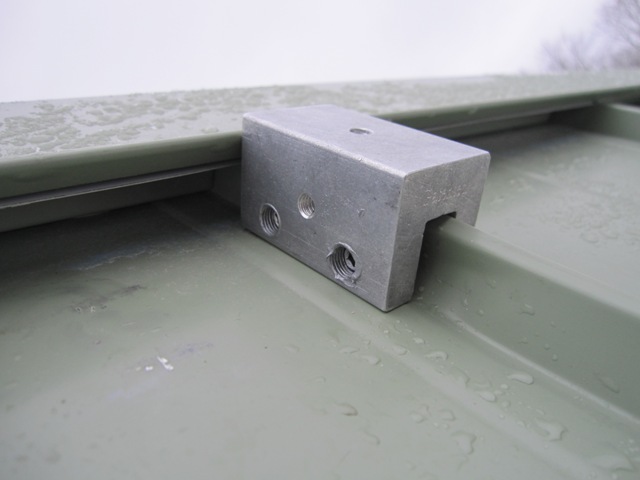
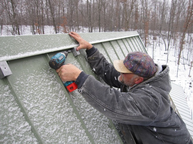
Dan and Bruce began attaching the clamps to the metal roof. Here are two photos showing how the clamp seats around and crimps into the standing seam as the set screws are tightened. Typically these clamps will hold several hundred pounds each, and our panels only apply about 20 pounds to each clamp so they’re plenty strong.
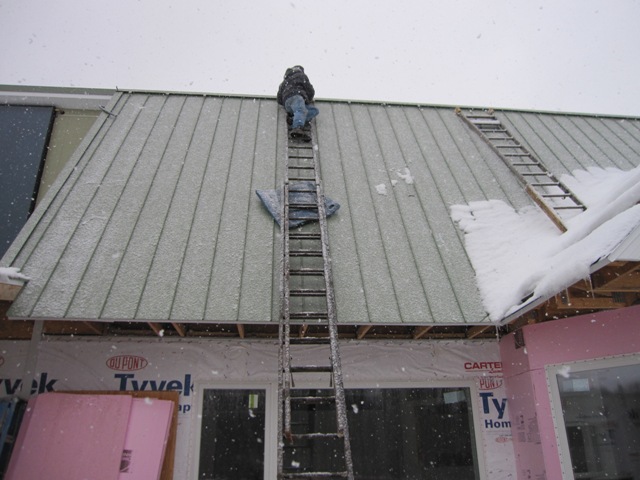
Here’s Dan up on the ladder attaching the clamps to the roof. We used a torque wrench to calibrate the cordless drill to tighten the set screws with sufficient torque, and used a U-joint made for sockets so that the drill could tighten the set screws from a slight angle. The clamps are applied every other rib, for a 24-inch spacing as required in the mounting instructions provided by Evergreen Solar.
December 17, 2009
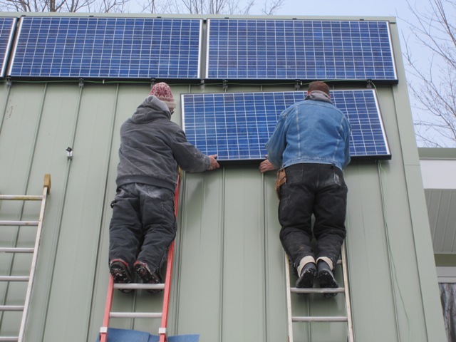
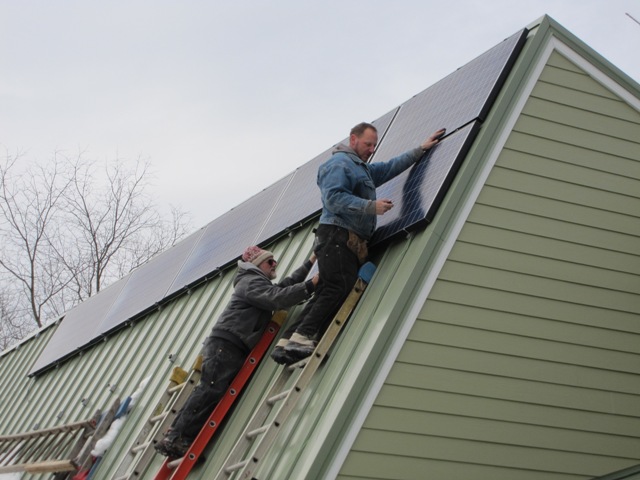
At last Dan and Bruce raised the first panel and clamped it in place. Each panel will get either two or three pairs of clamps depending on how it happens to fall on the 24-inch clamp spacing.

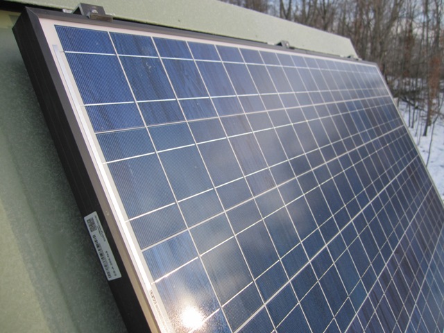
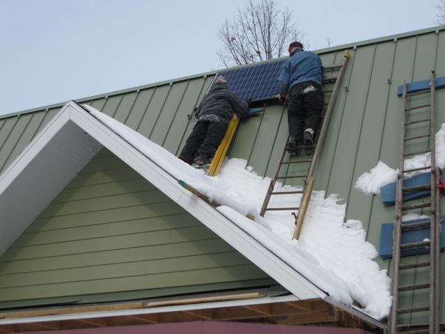
Here’s a photo of them raising the second panel into place. You can see the wire pigtails hanging out from lower left of the panel that’s already mounted. These just snap together in order to connect the panels in series.

After the first two panels were up, Jay decided that the spacing didn’t look quite right. So Dan and Bruce mounted the top-center panel next, in order to space the other panels right and left of it with the same 1-inch spacing that the clamps will impose between subsequent rows. This will space them a little closer together than before and the two panels on the right in the second photo below will have to shift a few inches leftward, framing the whole array with a narrow border of roof visible on the right and left ends. It’s not just about the energy – it has to look pretty too!
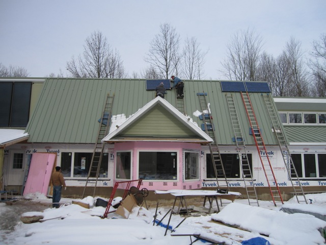
After the first row of 5 panels was done, they lowered the ladders and started on the next row down. The technique was to use a spacing board to first set the clamps at the proper distance below the row above, so that they could set the panel onto the lower clamps to support it. Then they had to reach up and tighten the clamps above between the two rows of panels, where each clamp grips both the panel above it and the one below it.
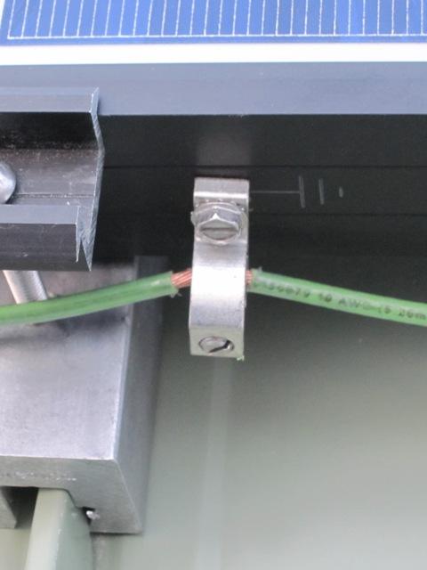
The electrical code requires that all the panels are grounded together, with a continuous ground wire that permits any one panel to be removed without breaking the ground connection to the others. This is accomplished with a special grounding clamp designed for this purpose. You can’t see it in this photo, but the bottom of the clamp is open to allow the wire to be inserted or removed. This is a continuous wire that runs to every panel in each half of the array and back to the grounding point at the inverters on the rear of the house. The wire must be no smaller than the current-carrying conductors, 10-AWG in this case.
December 18, 2009
They continued mounting panels today, and this photo shows one-half of the array completed. These 15 panels form one string, which is wired to one of the two inverters. The other 15 panels will form a completely separate string wired to the second inverter.

December 19, 2009
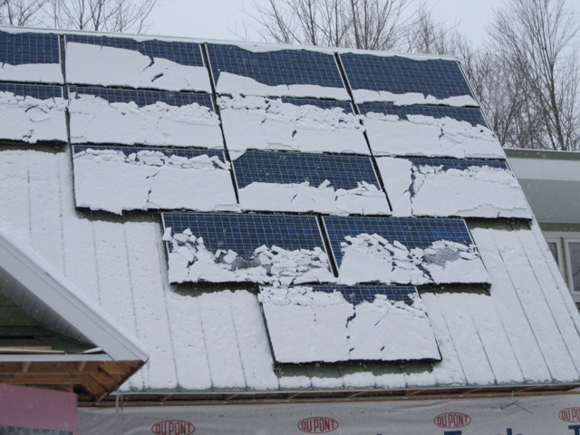
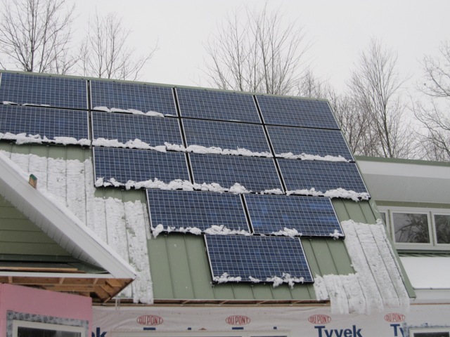
We had a light snow overnight, and in the morning we could see how the steep 60-degree slope helps the panels shed snow. The first photo below was taken at about 11:30 in the morning, and the second photo shows that even with only weak sunshine the panels were nearly clear by 3:30.
December 21, 2009
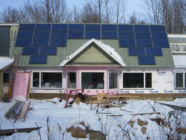
As it happened, the last panel was mounted in place on the winter solstice. The second photo below was taken the following day around noon, when we had some weak sunshine. Too bad the pink foam insulation spoils the color scheme, but we think it looks pretty good nonetheless.

February 3, 2010
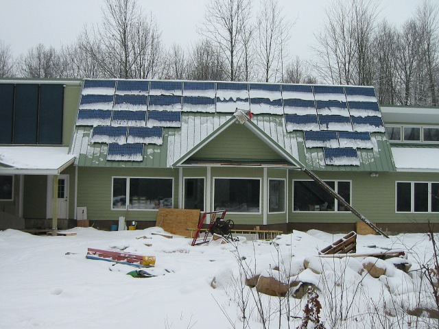
The siding is finished on the south side, and the panels continue to shed snow quite well. This photo was taken in the morning after a light snow, and the panels were clear of snow by mid-morning.
March 5, 2010
We have waited a month and a half for the power company to go ahead with the grid connection for the solar electric system. The photos below show the dual meter socket and breaker box that connects to the inverters. The meter on the right is our regular electric meter, and the one on the left will measure the solar energy delivered to the grid. Although it was approved quite a while ago, it took about a month for them to get those big yellow stickers and they wouldn’t proceed without them.


The photo below shows the two Xantrex GT-3.3N inverters that convert the direct current coming from the solar panels into alternating current that is fed into the power grid. Our array of 30 panels is wired as two independent strings of 15 panels, with each string connected to one inverter. The system is fully functional but it remains switched off while we await final approval from the power company. However we did perform a brief test of the system as required by the power company, and it delivered just over 5000 watts AC on a mostly sunny day with a bit of haze. The panels are rated at 6150 watts DC under ideal test conditions and at best the inverters are only about 95% efficient, so we’re quite happy to get over 80% of rated power on a day that wasn’t even full sun.
