The solar heating system will use a 2500-gallon water tank to store the heat collected from the Solar Heat Collectors. The tank is 8 feet in diameter and 7 feet high. We could get by with a smaller tank, but using a large tank like this will keep the operating temperature of the system lower which makes the collectors more efficient. It also gives us the potential to store heat over a longer period of time, with up to one million BTU of usable energy storage. That’s enough to heat the house for nearly a week, depending on the outside temperature, so it’s not nearly big enough to collect heat in the summer and use it in the winter but it’s enough to get us through a week of cold cloudy weather if it starts out at full temperature. This polyethylene tank is rated at 140 degrees F max, so the solar collection system will have controls to make sure the tank temperature stays below that limit. Click here for a discussion of how the solar heat storage system was designed.
September 21, 2009
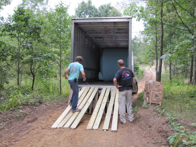
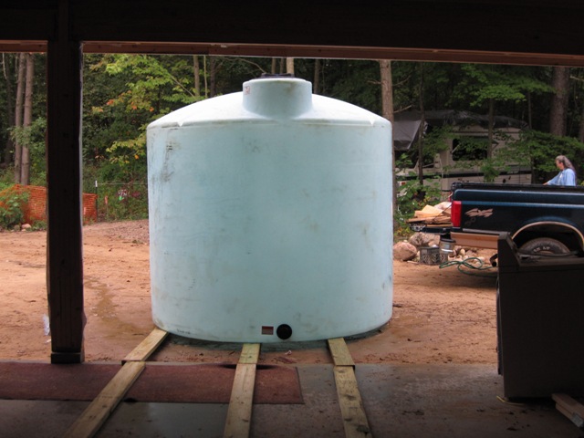
The big tank arrived inside a big truck. Our inspection revealed some small cracks along the bottom rim, so we initially refused delivery. After the vendor assured us that these are normal and won’t lead to tank failure, we reluctantly agreed to accept it. This is a commercial-duty tank that weighs about 450 pounds but it was fairly easy to roll it down planks out of the truck, and up the driveway to the garage. Standing it upright took a little more muscle but it was manageable with three of us.
October 29, 2009
The water in the tank won’t flow anywhere; it just sits there in the tank absorbing and releasing heat. In order to heat the water in the tank using the solar collectors, and to later use that heat in order to warm domestic hot water and the floors, the tank has four heat exchangers in it. Each heat exchanger is a 100-foot-long coil of 3/4″ copper tubing inside the tank. Two coils are for the hot fluid coming from the solar heat collectors, which warms the water in the tank when the sun is shining. One coil is for domestic hot water, and it warms up the water coming from the well to provide hot water for fixtures in the house. The the fourth coil warms the water that flows through the tubing in the heated floor slabs.
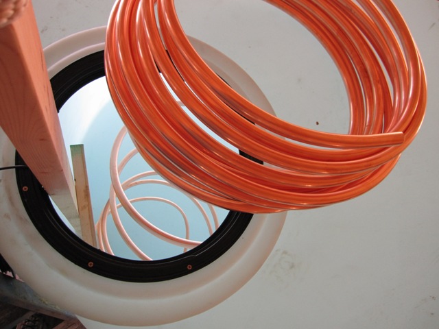
There is a 16-inch diameter hatch in the top of the tank, through which a slim person can just fit. In order to make the heat exchangers, we spiraled the copper tubing coils down through the hatch one at a time. It was a two-person job, with person one atop the tank feeding the tubing in and the other person inside the tank coiling it up on the floor.
November 1, 2009
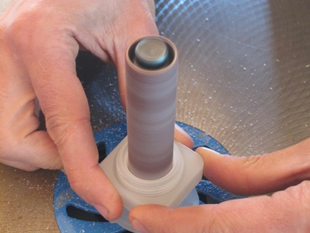
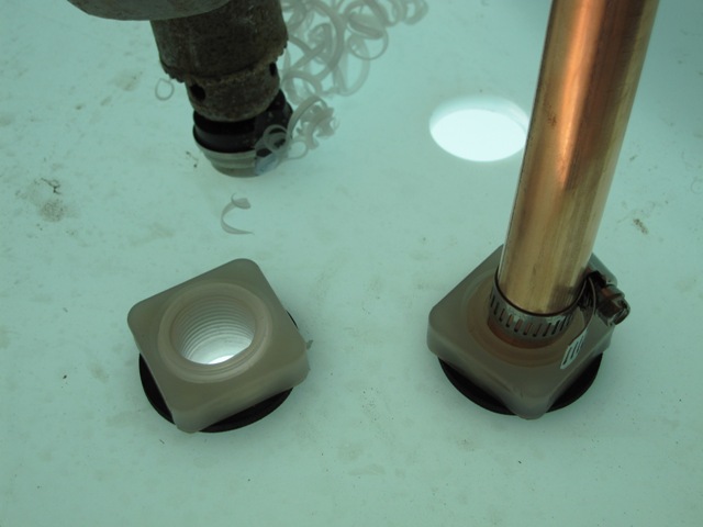
With four heat exchanger coils, we needed eight openings for the ends to pass through the top of the tank. Because the fluid coming from the solar collectors can get quite hot, up to 180 degrees F, we used polypropylene bulkhead fittings from U.S. Plastic Corp. to insulate the tubes from direct contact with the tank wall. The polyethylene tank is only rated up to 140 degrees F, while the polypropylene fittings can take up to 200 degrees. In order to fit the 3/4″ tubing through the fittings, they were enlarged slightly with an oscillating spindle sander. Then holes were drilled through the top of the tank with a large step drill and the fittings were installed. Hose clamps prevent the end of the copper tubing from slipping back in. Later we’ll seal the connection with silicone caulk. These are above the water line so they won’t leak water, but we don’t want any water vapor escaping into the cellulose insulation that will cover the tank.
November 6, 2009
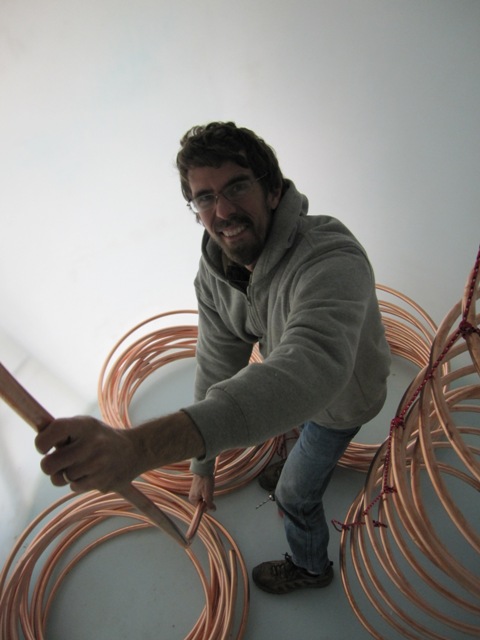
Once the coils were inside, each was pulled up vertically like a spring and supported on polypropylene ropes suspended from the tank roof. In order to avoid leaks there are no copper connections inside the tank, only continuous lengths of copper tubing. The first photo below shows the first heat exchanger Jay made. The shape is a bit “artistic” but it should work just fine. Jay spent a lot of time down in the tank bending all the coils and tying them into place.
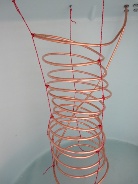
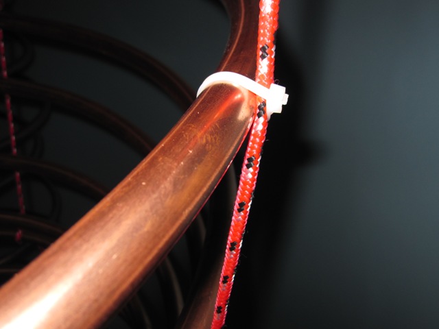
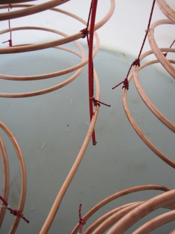
The first photo below is a close-up of a rope support at the top of the tank. All the hardware is stainless steel to prevent corrosion, and it’s sealed with silicone caulk to prevent any release of water vapor. The second photo shows how the ropes are tied on to the copper coils.


It did not seem necessary to knot the rope around every turn of the coil because the copper is fairly stiff, so the ropes were tied on approximately every third turn of the coil and this seemed to support it well. But in places where a rope might rub on the copper, a nylon cable tie was used to secure it so that it won’t wear down the copper over time.

November 8, 2009
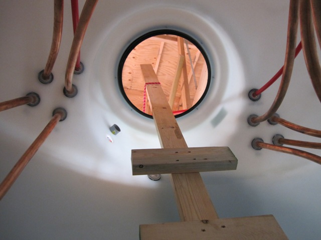
All four coils are now in place. In the first photo below, which was taken looking down through the hatch, the coils at the upper right and lower left will be for the solar collector loop that heats the tank. We’ll run the fluid through both of these coils in parallel, to provide double the surface area and increased flow rate compared to using just a single coil. The coil in the upper left is for domestic hot water, and the one in the lower right is for heating the floors. The coils are positioned such that no loop touches another, so that any movement caused by changing water flow won’t cause any abrasion of the tubes. The second photo, taken from inside the tank, shows the tubes passing up through the fittings in the top.

November 13, 2009
The device that controls the pump to circulate the fluid through the solar collectors needs to sense the temperature at the top and bottom of the tank, so that it only circulates fluid when the collectors are warmer than the tank water. The temperature sensors will be inserted into PEX tubes that are positioned as shown. The first photo shows the sensor tube at the top of the tank, ending about 8 inches below the top of the water. The second photo shows the tube running to the bottom of the tank, ending about 6 inches above the bottom. Because the sensors are not waterproof. the ends of the tube are sealed with watertight plugs.

November 15, 2009
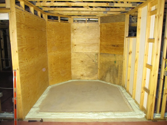
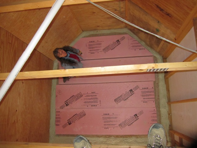
The tank will sit in a compartment at the back of the garage, between the garage and the main house. Inside the house these walls will be covered with drywall, and in order to prevent drywall cracking from temperature fluctuations or any possible moisture problems, we put plywood on the inside of the tank compartment. The concrete floor slab on which the tank sits is isolated from the main floor with foam insulation, so any settling won’t affect the floor of the main house and it won’t conduct heat directly into the main floor. That will be important in the summer! Although there’s already 6 inches of foam under this slab, We put an extra 3 inches on top to further reduce heat flow down into the ground.
November 16, 2009
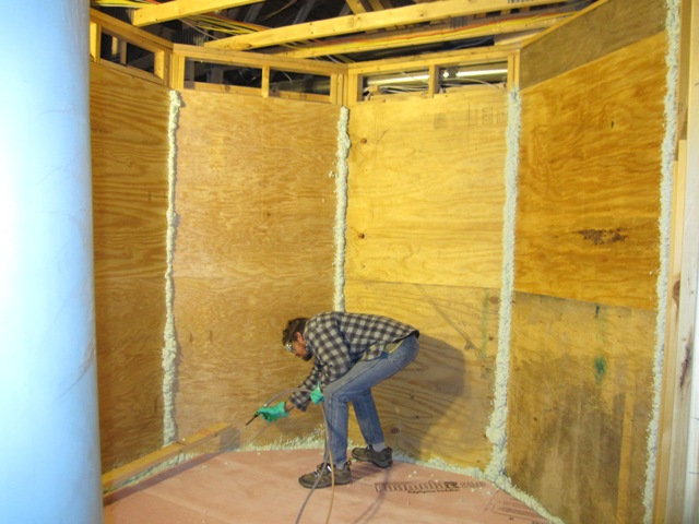
We used spray foam to seal the seams of the plywood walls and around the base. This probably wasn’t necessary but we had some spray foam left over and this seemed like a good place to use it up.
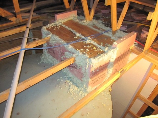
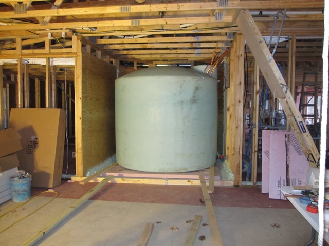
With the compartment prepared, we pushed the tank into place by sliding it on 2x4s. The tank itself weighs about 450 pounds plus about 200 pounds of copper tubing, and it was possible for two people to push it along the 2x4s. The second photo shows the view from up in the attic, looking down through the trusses. This compartment will be walled off from the garage and filled with cellulose insulation.
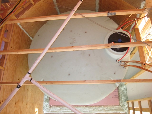
November 18, 2009
We filled the tank using a garden hose. Our well produces about 10 gallons per minute so it took about 4 hours to fill it. The total capacity is 2500 gallons but we can’t fill it right to the top so it actually holds about 2300 gallons. Including the tank and the copper tubing, that’s about 19,000 pounds of thermal mass! Both of these photos were taken looking down through the hatch.
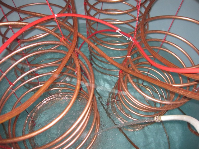
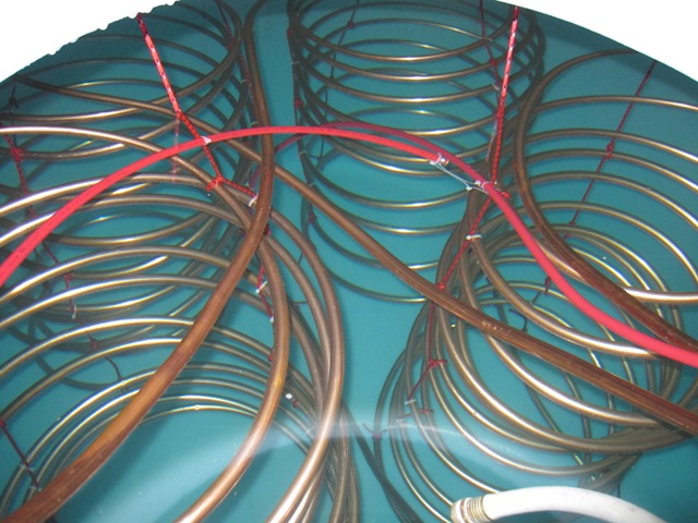
November 19, 2009
Here’s a photo of the drain valve at the bottom of the tank. This is an emergency drain, which can dump the tank water into the garage (where it will run out the garage door) in the event that we need to drain the tank in a hurry. This valve will be accessible through this opening from the mechanical room. A plywood box surrounds this area in order to exclude the cellulose insulation, and we’ll stuff it with fiberglass so we can get to the valve if needed.
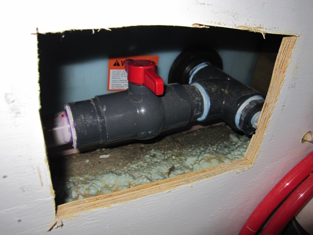
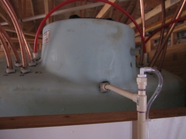
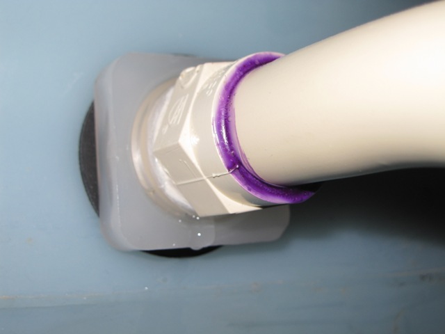
After filling the tank last night, we checked very carefully for leakage at these fittings. The fittings on the drain valve were just fine, but alas there was a minor leak up above. The first photo below shows the overflow pipe, which makes sure that the water level never gets as high as any of the other fittings at the top and also allows the tank to “breathe” as it changes temperature. The clear tube is a water level indicator, which comes from the fitting shown above. The second photo shows the leak. It’s actually leaking where the CPVC fitting threads into the bulkhead, and also around the rubber gasket of the bulkhead fitting. We’ll need to correct this, as water leakage would be bad once this compartment is filled with cellulose insulation.
November 19, 2009
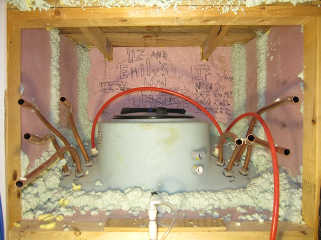
All the fittings and the hatch will be sealed soon, but there’s still a possibility of water vapor escaping through a leaky fitting and it would be bad if it were to permeate into the cellulose insulation around the tank. We want this area to breathe, so that any escaping water vapor can dissipate. After bending all of the 3/4″ copper tubing out into the mechanical room, we built a plywood and foam box around the hatch and fitting area in order to keep the out the cellulose insulation when it’s installed. The plywood on top rests on the trusses to provide overhead support, and the sides are made from 3″ foam board all glued together and sealed with spray foam. Our grand-niece Emily decorated the back piece before it was installed. After all the plumbing connections are made we’ll fill this space with fiberglass batt insulation, which will allow water vapor to exit if needed. The fiberglass can be removed easily if we need to access the fittings or hatch for any reason, without disturbing the cellulose.
